 Reddit reviews Leviton 47609-EMP Telephone Patching Expansion Board
We found 3 Reddit comments about Leviton 47609-EMP Telephone Patching Expansion Board. Here are the top ones, ranked by their Reddit score.
Use with category 5e voice and data board and/or telephone line distribution boardFits easily into any Leviton structured media enclosure4-Line bridged module with patching via modular plug, not 110 IDC punch down2 Year limited warrantyCompact Series Panels are ideal for multi-dwelling units and apartments or any place where space and budgets are of great concern
You will need to buy :
8-port Gigabit Ethernet Switch
An Ethernet patch panel
A punch down tool
A package of at least 6 1-foot Ethernet patch cables.
I am assuming your FIOS router is somewhere near the panel in the pics, because when you are done, you will need to run an Ethernet cable from the back of the FIOS router to your new 8-port Switch. The router doesn't have to be in the same room, but wherever it is, you do have to connect it via ethernet to the Switch.
Instructions :
1). The rooms all terminate into the left-hand panel, you can see the wires at the bottom in the pic. Each ethernet run will have 4 pairs of wires. Currently they are connected to the left-hand board, and then patched over to the right. Telephone wiring only requires a single pair for each line, currently you have 4 pairs to each room. What you need to do is first, buy a LAN line tester. Something like this :
https://www.amazon.com/Sperry-Instruments-TT64202-Cable-Tester/dp/B004Y75B5Y
You don't need to buy an expensive one, that is simply the first one which came up when I googled it. They are very easy to use, you just plug one half into a wall jack via the supplied 6-inch patch cable, and the other half into the matching port on your panel (left-side). Or you could disconnect the RJ45 connector from the matching right-side panel, and plug that directly into the tester. When you turn the tester on, it will tell you if the wires are correctly configured for Ethernet. It is almost certain they are not as telephone config is not the same as Ethernet config. If all 4 lights don't go green, that means you need an Ethernet patch panel. Likely only one light will turn on indicating only 1 pair was found (that's OK, read on...).
Here is what you are going to need to buy :
https://www.amazon.com/Steren-550-030-FastHome-Data-Hub/dp/B000EHW88Q/ref=sr_1_11?keywords=ethernet+patch+panel&qid=1573655221&s=electronics&sr=1-11
Again, doesn't have to be that one, but that is designed to provide RJ45 ports for Cat5e which is exactly what you have. Read the top comment on that page, someone named Daron Levy. That person did exactly what you need to do and even provided a shopping list of tools.
2). Remove the cover off of any Ethernet jack in your house, like the one in the first picture. Figure out which wiring config was used to attach the wires, either 568A or 568B. The back of those female ports all have a diagram showing the two possibilities, the only difference is the orange and green pairs are interchanged (brown and blue are the same in both A and B). You should be able to tell which was used by matching up the diagram on the port to the wires you can now see. Once you figure out which was used, use that everywhere.
3). It is not difficult, but what you need to do is detach each of the sets of wires from the phone board on the left hand side. That will give you 4 sets of wires per room. Using a punch-down tool, punch the wires into the new Ethernet patch panel using either 568A or 568B configuration, whichever one you figured out was used in step 2.
4). After the first room is punched into the new patch panel, test it with your tester. If you get all 4 green lights, you have successfully connected the line. You now have ethernet from your new patch panel to your room.
5). Plug a 1-foot ethernet patch cable into your newly working jack on the patch panel, and the other end into a 4 or 8-port switch. Then plug the Switch via Ethernet into your Fios router, and you should be golden. Repeat for each room.
​
​
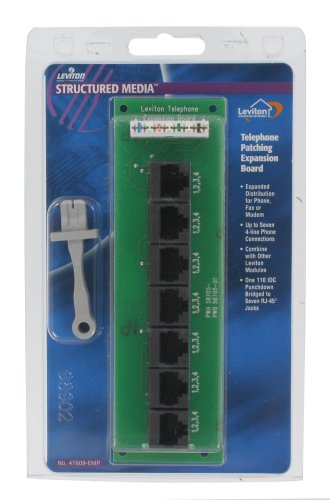
Here are the details of your telephone patch board :
https://www.amazon.com/Leviton-47609-EMP-Telephone-Patching-Expansion/dp/B000U3BVNW
​
EDIT - One more thing to add. Do not assume you can reuse those patch cables I see in your picture, they are almost certainly telephone patch cables with RJ45 connectors. They look like Ethernet, but are not. Use your tester, take any one of them and plug it in between both sides of your tester, I am willing to bet that all 4 green lights will not light up. Instead you'll get at most 2 green lights indicating they are wired for phone connections, not for Ethernet.
4- that knob and tube on top. Is it still active?
You should have just ran another ethernet drop in place of Cat3. Use something like http://www.amazon.com/Leviton-47609-EMP-Telephone-Patching-Expansion/dp/B000U3BVNW and have patch cords to route wherever you want a phone.
If I remember right they're just a splitter, there's no electronics on the board. You should be able to use a phone distribution block like this.
The Monoprice system is functionally equivalent to the Dayton DAX66, you might be able to get one from them. Their version just has screw downs for the keypad connections instead of the RJ45's.