 Reddit reviews Tolako 5v Relay Module for Arduino ARM PIC AVR MCU 5V Indicator Light LED 1 Channel Relay Module Works with Official Arduino Boards
We found 21 Reddit comments about Tolako 5v Relay Module for Arduino ARM PIC AVR MCU 5V Indicator Light LED 1 Channel Relay Module Works with Official Arduino Boards. Here are the top ones, ranked by their Reddit score.
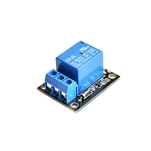
Microcontroller development board can be used as modules, can be used as appliance control5V - 12 V control signal of the TTLControl DC or AC signals can control the 220V AC Loadthere is a normally open and open normally closed contactUseful to control a motor, a led strip, or any other module using arduino. How to use it: Just connect a digital output of your arduino to your relay module, and you can control a power-demanding appliance with the digital signal provided by your arduino.
This is a really cool idea! Once you have this working you really need to post a "How-to", I think a lot of people would like something like this for their driveways. You could even have your speakers say "car entering driveway" or something when someone pulls up. Anyways, for the how-to (source, I'm an electrical engineer but 'non practicing', so I'm somewhat good with this stuff but not an expert):
I believe the door sensor works by sensing when the loop of wire is closed, vs having a contact voltage applied to it. You can test this easily by just touching the two terminals together with a piece of wire, and seeing if it properly triggers. If this is the case, you may need to incorporate a small relay into this project to close the sensors together. To trigger the relay, you could use the voltage from every time the LED is triggered.
You'll need a simple voltmeter if you don't have one already. These are very cheap and helpful to have around the house. Here's one that's cheap and seems to get good reviews. Use this to measure the voltage across at the LED when it's 'on'. If this is 5V-12V, you can use this relay which is for simple arduino projects, and is controllable via TTL signals.
You would connect the + and - terminals on the back of that relay board to the power supply in the driveway module you have. That provides power to the relay board. The, figure out which pin is driving that LED (the line will go from 0V to 5V when it triggers), and connect a wire to the 'S' pin on the back of the relay board. Now, when the LED changes to the on position, it will also flip your relay 'closed'. Simply connect each relay output terminal (front of the relay board) to the door sensor, one to each side. Now when the relay closes, it should also trigger your door sensor.
Hopefully this makes sense... let me know if you have any questions and good luck! Soldering is not all that hard once you get the hang of it. Just remember that you're trying to heat up the components metal contacts, and then apply solder to that (vs applying solder iron directly to the solder). This prevents cold contacts, which can break overtime.
If you refer to this line,
> For the pusher, I recommend a relay rather than a mosfet half bridge. Much easier to wire up and work with.
I wasn't referring to the motor, I was refer to what you use to control the motor.
That said, you absolutely do want to replace the stock motor.
Not only do you remove the risk of the motor burning it, but the pusher becomes much more responsive and controllable. Especially important if you want proper select fire, but just as useful in full auto.
As for what to use to controller the motor....
Since you want an microprocessor to control it, we can't just use a microswitch like in a standard build.
There are two main options.
An electromechanical device.
Exactly the same as a microswitch, but instead of being pushed by a finger, there's no button.
Instead, there's a solenoid which pushes the switch closed.
Can be obtained on their own for very cheap, and very small, or in bulkier, but easy and ready to go packages.
See https://www.amazon.com/dp/B00VRUAHLE/ref=cm_sw_r_cp_apa_Pt2rAb6Z63HVK for an example.
Allows you to easily make the motor either brake, or run. Aka, easy pusher control.
The relay itself has no risk of being damaged by ESD, it's just a coil of wire and a microswitch.
Slightly bigger than a mosfet. Can't control RoF like you can with a mosfet, but there isn't much of a reason to do this.
I probably could have been more specific, I am using a relay module (https://smile.amazon.com/gp/product/B00VRUAHLE/ref=oh_aui_detailpage_o09_s00?ie=UTF8&psc=1) to toggle the solenoid, connected to the Arduino's ground, 5 V and D4 signal pin.
It's called a relay. They are cheap. here is a 5v relay. you can get them in multiples, with multiple current ratings.
Just put one inline with a wall switch. They are small enough to fit in the switch box.
If you want the switch to always invert the state, (i.e. If light is on, and switch is down) you could hook the wall switch up to gpio and have it swap the state of the relay for every switch state change. This way you won't run into a situation where you want to manually turn off the light but can't because it was remote controlled.
Items:
https://www.amazon.com/Tolako-Arduino-Indicator-Channel-Official/dp/B00VRUAHLE/ref=sr_1_3?ie=UTF8&qid=1522213485&sr=8-3&keywords=5v+relay
If you need to save on some space, go with a Solid State Relay like this:
https://www.amazon.com/G3MB-202P-DC-AC-Solid-State-Module/dp/B01JCPPBI4/ref=sr_1_3?s=industrial&ie=UTF8&qid=1522213949&sr=1-3&keywords=5v+solid+state+relay
and
https://www.amazon.com/CO-RODE-Battery-Holder-Wired-Switch/dp/B00VE7HBMS/ref=sr_1_8?ie=UTF8&qid=1522213257&sr=8-8&keywords=small+12v+battery
or
Get this and a 3x AA battery holder for your 11.1 volts
https://www.amazon.com/WAY%C2%AECharger-2000mAh-Rechargeable-Batteries-Flashlight/dp/B00PIDNTRA/ref=sr_1_3?s=electronics&ie=UTF8&qid=1522213739&sr=1-3&keywords=Lithium-ion+AA
and
https://www.amazon.com/Gfortune-Cable-Plastic-Batteries-Holder/dp/B06XW8QC6N/ref=sr_1_3?s=electronics&ie=UTF8&qid=1522213842&sr=1-3&keywords=3+cell+aa+battery+holder
It's pretty simple if you use a 5v relay. You can think of a 'relay' like a light-switch that can be turned off and on with a digital pin on the arduino. You will actually hear a mechanical 'click' when you trigger it.
So you can use a 5v relay like this one to control a 12v power supply like this one.
And then wire it up with your light like this.
​
Let me know if you have any questions about how to use the relay properly.
OK got it. I hope you don't mind all my questions. Hopfully this is the last of it.
I have amazon prime so is this close enough to your link above: https://www.amazon.com/Tolako-Module-Arduino-Official-Boards/dp/B00VRUAHLE/ref=sr_1_1?ie=UTF8&qid=1474495841&sr=8-1&keywords=5V+to+12v+relay
Also, what end would I connect the 5v to trigger the other end 12v?
Thanks again!
This is the relay that triggers the on/off button, but any 5V relay works, it doesn't have to be high voltage. I don't know about the other one, I just found it laying around. Here's a picture of it more in focus. It doesn't have to be anything fancy, if it's rated to handle household current it's plenty good.
I ordered this relay module online in hopes i could use it to control the electromagnet. Would this work instead of a mosfet. I could solder the 12vDC electromagnet into the 12v adapter wires to power it and the arduino from the same source? https://www.amazon.com/gp/product/B00VRUAHLE/ref=oh_aui_detailpage_o00_s00?ie=UTF8&psc=1
And this is the magnet i ordered:
https://www.amazon.com/gp/product/B00JERC00S/ref=oh_aui_detailpage_o00_s00?ie=UTF8&psc=1
I got this relay board:
https://www.amazon.com/gp/product/B00VRUAHLE/ref=oh_aui_detailpage_o00_s00?ie=UTF8&psc=1
I actually bought a 0.96" OLED screen that I might add to display when the plant was last watered.
Arduino
Raspberry Pi
Pump
Relay
Sensor
My fireplace (like most gas fireplaces in the US) just needs a circuit to close to turn on. I had a wall switch doing this, I replaced that with a HomeKit outlet, a 5v DC wall wort, and a $6 relay. All that stuff is under the fireplace. I didn’t even know what a relay was when I started, but this was much easier than I thought it would be.
The relay: Tolako 5v Relay Module for Arduino ARM PIC AVR MCU 5V Indicator Light LED 1 Channel Relay Module Works with Official Arduino Boards https://www.amazon.com/dp/B00VRUAHLE/ref=cm_sw_r_cp_api_i_OAMRCb29M6G8J
You could try rigging it into a relay such as this one, then powering it with a 9v battery. It may take some fiddling, and I'm way too tired to think right now, but it could work. I used it to hook a lamp up to an arduino and powered it with much lower voltage than the lamp would normally take. Of course, you'll still have the normal issues you'd get by using a doorbell circuit.
If you really want to get it done you could wire up a killswitch with a doorbell looking button, and add an LED that is controlled by the killswitch button.
It's specifically made for Arduino with a FET on board for the control pin and I'm powering the coil (not the switched load, the relay coil itself) from a separate 5V/2A power supply. It's schematically identical to this one - note the J3Y transistor on the side.
Others have mentioned that I I needed to declare the pinMode for output (narrator: he didn't), which I'll be checking later.
You probably want to ask over at r/raspberry_pi. I have completed projects with power switching and would probably recommend using a relay. You can still use python to turn the relay off and on... And it's kinda the whole point of using a pi for this type of project. Here is an [example project] (https://elementztechblog.wordpress.com/2014/09/09/controlling-relay-boards-using-raspberrypi/) (not mine)...
Alternatively, you could use a pump like this combined with a motor controler you would get much more precision over the flow.
You'd be fine if you used a relay such as this one. It has a transistor to protect from back voltage to the Pi and is really easy to use. I've set one up in the past to control a lamp with my cell phone.
That depends on the size of your motor, the digital pins on the arduino can provide 40 milliamps of 5v power, but given that your motor is out of a car I suspect it requires 12v to operate, at a substantially higher current. For the purposes of your demonstration I you can either get a 12v battery box, or a 12v wall transformer and just say that in a production run the motor would be run by the car's 12v electrical system. Then use a relay to control the power to the motor.
The two servos and linear actuator Im using are all getting power directly from the 12v power source. The only things connecting these items to arduino are their signal lines and ground.
Im actually not sure how much current Im drawing from the 5V rail. The only things being powered by the +5V rail are three of these photosensors, two of these relay boards (to change the direction of the linear actuator), and two limit switches with 10k ohm pull-down resistors. Ill try to find my multimeter and see if this is the problem.
If I was drawing over 150mA from the 5V rail, wouldnt my arduino overheat even if it was plugged into the USB of a computer? Because right now it's fine if I keep it plugged into the computer and dont have 12 going directly to Vin.
2 5v triggered arduino relays will get you to 1P4T
You could also use a relay board. They work out of the box with no soldering and you can get boards with up to 16 relays.
https://www.amazon.com/Tolako-Arduino-Indicator-Channel-Official/dp/B00VRUAHLE/
This is the relay you are looking for (allows you to control any 120V AC load at 10A):
https://www.amazon.com/Tolako-Arduino-Indicator-Channel-Official/dp/B00VRUAHLE/ref=asc_df_B00VRUAHLE/?tag=hyprod-20&linkCode=df0&hvadid=309803885710&hvpos=1o2&hvnetw=g&hvrand=3454667229330550267&hvpone=&hvptwo=&hvqmt=&hvdev=c&hvdvcmdl=&hvlocint=&hvlocphy=1014421&hvtargid=pla-568715033020&psc=1
This is a really common thing to do with an Arduino, you can learn more about it here:
https://www.instructables.com/id/Home-Automation-How-to-Add-Relays-to-Arduino/