Best car amplifier heat-shrink tubing according to redditors
We found 53 Reddit comments discussing the best car amplifier heat-shrink tubing. We ranked the 11 resulting products by number of redditors who mentioned them. Here are the top 20.
We found 53 Reddit comments discussing the best car amplifier heat-shrink tubing. We ranked the 11 resulting products by number of redditors who mentioned them. Here are the top 20.


I use these at work in marine environments:
http://www.amazon.com/3M-Heat-Shrink-Connector-Piece/dp/B008HMHJDO
Over that I apply more heat shrink. Holds up pretty well.
Alternatively, invest in some Heat Shrink Butt Splices
Much less messy and far sturdier than twisting and wrapping with electrical tape. You just insert each end of the wire, crimp, and hit it with some heat to seal it. This way is weatherproof, electrical tape isn't.
You don't need to slip over the connector, the heat shrink is already on the butt splice. You crimp then heat and it shrinks down and seals everything. There's a coating of glue the melts and oozes out. But you need to make sure you have a good crimp too, cheap ones will break or cut the heat shrink when you crimp. The glue also helps hold the wires in place. If you shrink it down without crimping, you'll still need to apply some force to rip the wires out.
https://www.amazon.com/3M-Heat-Shrink-Connector-Piece/dp/B008HMHJDO
This is the drone that I have built:
Been slowly building my first quad over the past month or so. Just when I have time. I bought a cheap carbon fiber kit off amazon. I will list everything I have bought so far.
Fly Sky FS-i6 Transmitter https://www.amazon.com/gp/product/B00VE3PZ3Y/ref=oh_aui_detailpage_o04_s01?ie=UTF8&psc=1
Fly Sky FSia6b RX (need this to run PPM instead of PWM): https://www.amazon.com/gp/product/B00VE3Q3XU/ref=oh_aui_detailpage_o02_s00?ie=UTF8&psc=1
LHI quad Kit with ESC's, Motors and Flight Controller: https://www.amazon.com/gp/product/B010FMGUS8/ref=oh_aui_detailpage_o04_s00?ie=UTF8&psc=1
Now the above kit comes with a CC3D flight controller, after some research, I decided that I would use a Naze32 rev6 board instead. I purchased that from Hobby king, I will list all hobbyking purchases after amazon.
Nylon hex nuts, screws and stand offs:
https://www.amazon.com/gp/product/B01EPLH08Y/ref=oh_aui_detailpage_o03_s00?ie=UTF8&psc=1
XT60 connectors: https://www.amazon.com/gp/product/B01E9HM7NC/ref=oh_aui_detailpage_o03_s00?ie=UTF8&psc=1
Lipo Voltage Checker: https://www.amazon.com/gp/product/B01E7UXVL8/ref=oh_aui_detailpage_o03_s00?ie=UTF8&psc=1
Battery / GoPro straps: https://www.amazon.com/gp/product/B01F7MEDW6/ref=oh_aui_detailpage_o01_s00?ie=UTF8&psc=1 PS: good velcro isnt enough!
Tri-blade Props. Buy a couple of these!:https://www.amazon.com/gp/product/B01CHDNRRK/ref=oh_aui_detailpage_o00_s00?ie=UTF8&psc=1
Extra arms....JUST IN CASE! https://www.amazon.com/LHI-Carbon-thick-250mm-Quadcopter/dp/B01715HGNU/ref=sr_1_1?ie=UTF8&qid=1472346179&sr=8-1&keywords=LHI+arms
These are all the hobby king stuff that I bought:
Naze 32 FC ACRO: http://www.hobbyking.com/hobbyking/store/__96841__AfroFlight_Naze32_Rev6_Flight_Controller_Acro_.html
1300 mah 3s 45-90c lipos: http://www.hobbyking.com/hobbyking/store/__18207__Turnigy_nano_tech_1300mAh_3S_45_90C_Lipo_Pack.html
Besides a lipo charger, the above will get you flying! Below is everything needed for the FPV aspect! I used to run RC cars so luckily I had a lipo charger from those days
Camera and transmitter from ebay: http://www.ebay.com/itm/262061528376?_trksid=p2057872.m2749.l2649&ssPageName=STRK%3AMEBIDX%3AIT
Clover antennas from ebay: http://www.ebay.com/itm/272297376391?_trksid=p2057872.m2749.l2649&ssPageName=STRK%3AMEBIDX%3AIT
Quanum Cyclops FPV Goggles from hobbyking: http://www.hobbyking.com/hobbyking/store/__104150__Quanum_Cyclops_FPV_Goggle_w_Integrated_Monitor_and_Receiver_AR_Warehouse_.html
Now this is prolly the most basic, beginners fpv setup that you can buy... Its perfect for learning and crashing lol. I have about 3 flights with mine so far, about 4 batteries. Buy props lol, lots of props. Already had to change 1 arm too.
It sounds like you did a bunch of research and you're totally ready for this bun!
Just a couple of specific ideas to add on to what the other commenters have suggested. This stuff is great for covering wires. If you find that the carefresh doesn't absorb odor as well, you can try a pelleted litter (I use oxbow eco-straw since it's safe for them to eat)
Congrats on your new bun!
You need:
1.) XLR connector like this: https://www.amazon.com/gp/product/B00067JJ8Q/
2.) Some long enough wire, for example: https://www.amazon.com/gp/product/B00UR0N370/
3.) One XT60 connector: https://www.amazon.com/gp/product/B01E9HM7NC/
4.) Some sort of quick disconnect plug, example: https://www.amazon.com/gp/product/B006ZOIJ0S/ (this is so that it can easily disconnect if you crash without damaging the cable)
Then just solder those parts together and you're ready to go.
PS: This case is optional but it perfectly fits 2 carvepower battery cases and the solar charger device + cable: https://www.amazon.com/gp/product/B01N6N3J8D/
You can drill and nut and bolt the L-Brackets through the floor pan, sure.
A pain to remove the box that way.
Better would be to slip a board under the carpet/liner; bolt that through the floor, and use insert nuts to add threads to the board that you can screw the L-brackets to.
And even better, you can use threaded rivets to screw directly into the metal floor pan
That involves buying another tool, though. There’s a cheaper version at Harbor Freight, but the rivets are soft and somewhat prone to spinning in the hole.
The easiest method overall is to just use a ratchet strap over the top.
....
Always check, double check where you’re drilling; and anytime you drill through painted metal, good to use touch-up paint around the hole or apply some grease to prevent rust.
....
It’d be better to mount the amp separate from the box; and you can use the same strategies to do so.
Add an XT-60 disconnect in-line on the subwoofer cable for easy box removal.
If you do want to put the amp on the box, place it in a corner or along an internal wall where the bracing is stronger.
They make butt connectors with adhesive shrink over them, those are my preferred goto. The ease if a quick crimp (still have to make sure the wires prepped right and you're using a quality crimper so it's not loose at the connection.) then a quick pass with a torch and it's weatherproof and solid.
Edit: Grote 83-2350 Heat Shrinkable Butt Connector https://www.amazon.com/dp/B00HFLE2JM/ref=cm_sw_r_cp_apa_i_nC2yCbJJ0FTKE
Just completely swap the connector to anything. https://www.amazon.com/Finware-Female-Bullet-Connectors-Battery/dp/B01ETROGP4/ref=sr_1_3?s=electronics&ie=UTF8&qid=1549167374&sr=1-3&keywords=xt+connector
They make these in various sizes and you could replace it again if it ever breaks.
These connectors are the best type to use, especially if it's exposed to weather. I even tape or shrink wrap over these sometimes but it's not necessary.
If I have time and the project is appropriate or I can't spare extra bulk in a wiring harness, I'll skip covered connectors and use solder with bare metal connectors and shrink wrap.
Here's some that ship via Amazon Prime: https://www.amazon.com/dp/B01E9HM7NC/ref=pd_lpo_sbs_dp_ss_3?pf_rd_p=1944687442&pf_rd_s=lpo-top-stripe-1&pf_rd_t=201&pf_rd_i=B005FAPYXS&pf_rd_m=ATVPDKIKX0DER&pf_rd_r=QGZ6F6JXSQ8DRTGM8ADM
Perhaps wire loom? You should be able to buy it for a LOT less at your local Home Depot, Menards, Lowes, or auto parts store.
We made an enclosure out of foamcore boards and duct tape...they get chewed eventually, sure...but it worked better than this:
http://www.amazon.com/Marshall-Small-Pet-Deluxe-Play/dp/B0013TT2SS/ref=sr_1_1?s=pet-supplies&ie=UTF8&qid=1322368051&sr=1-1
Also, I got wire covers for everything like this:
http://www.amazon.com/American-Terminal-SL500-100-2-Inch-Tubing/dp/B0017686ZC/ref=sr_1_6?ie=UTF8&qid=1322368115&sr=8-6
For EVERYTHING...keeps the chewing down and keeps them from getting peed on. Also, every rat loves a buddy....
Buy some real 14 AWG silicone jacket wire, (this is what I'm using) and a set of quality XT60 connectors like these.
Ideally you want crimped ring terminals for all power leads that connect to screw terminals, putting bare wire into them isn't how they're meant to be used.
The 14 AWG has enough area so you can solder them to both positive and negative pads on the heatbed respectively, and terminate those with 1 XT60 connector. A word of advice - dismount your heatbed, flip it upside down and put it on something that can take some heat for a bit like corkboard. Heat it up to 60-80C, turn it off, then remove the stock connector and solder the wires. Otherwise you'll get nowhere trying to solder to a room temp heatsink.
The matching XT60 connector uses the same 14AWG to crimped ring terminals, going to the MOSFET board. For reference, here's one I'm using on my printer.
I only removed the power pins from my bed, I pre-cut the connector so I could leave the middle pins and connector shell for the temp sensor attached to the bed, then I could still use that to disconnect those wires. Works great because the little retaining mechanism is in the middle of the connector over the sensor wires.
Pre-tin the XT60 wire cups and the wire itself before you try to solder them together unless you've got both a beefy soldering iron and good soldering skills, otherwise your connector will end up with a faulty solder connection.
Now it's easy to disconnect the heatbed.
I bought these to cover up my cords. They've worked well so far.
https://www.amazon.com/Monoprice-107118-1-Inch-10-Feet-Flexible/dp/B001114AO4
Try using something like this to cover your cords if you don't intend on moving them too much. Buns and cords are not a good match. lol.
I think that's big enough for nights and unsupervised time. We have something like this that Novy used as a run when he was little. We got a second one and connected them together and that's what he uses when we're gone during the day now. He still goes up to his cage (2ftx5ft?) at night. When we're there he has roam of a few rooms and occasionally the upstairs.
We use cable wrap like this to cover ground cords. He's chewed on them a few times but there's no damage. As long as they're against the wall they'll be fine. For my computer desk I screwed a postal mail tube underneath it and split if length wise to stick the power strip in so it's up out of the way; as a bonus it looks better too!
For the bookshelf, we use gating that looks like the stuff from the pen I linked to above for temporary 'keep bun out' areas like that (in my case the entertainment center).
[Edit: Updated the cable wrap link, used the wrong one initially!]
This is where things get a bit weird for the Type 97. The official battery for them is wonky as fuck and requires the removal of the entire lower grip to install.
I, on the other hand, did some measuring and found these particular batteries. They fit perfectly in the grip, I'm not even kidding. Did some measurements with my calipers and these are the only batteries with the perfect proportions where you can slide the buttplate off the grip (normally reserved for the tool kit that comes with the gun) and slip it in there. However, as I'm sure you notice, you'll need to convert your gun to XT60. Not a difficult conversion, but it does require some patience, a soldering iron, and some connectors. I picked up this pack and it does me just fine
We have two cats that chew on wires (including phone chargers and headphone cables). Using something like this cord wrap stuff, makes it unpleasant to chew.
If it's useful, I too just got started, and built a similar drone. When it came to charging, I had to read a ton of stuff. Here's what I did (all non-referral Amazon links. you may find cheaper on banggood if you want to wait forever):
ISDT Charger
12v Power Supply
Balance Charger
To connect these up, it may be useful to have some extra XT60 plugs since the power supply won't have XT60, and neither does the balance charger.
With these optional parts, I was able to make a nice looking (and more safe) charger from the power supply, along with a 3d print available here
Voltmeter
Power plug
I found this to be a pretty fun project, and wasn't as expensive as some options I saw on HobbyKing or everywhere else. To be fair, it wasn't the cheapest option either.
This is a good start. There are many different sizes and brands but this is the one size I use. I got mine from Home Depot/Lowes though. Same stuff.
Buy a new coil wiring harness. They're notorious for failing. I bought some plastic wiring tubing (like this) at the local WMart and wrapped it in electrical tape before installing the new one (Hyundai Accent, but basically the same car). You can buy OEM parts on EBay direct from Korea fairly cheap.
YW!
I also use it on the UPPER part of the heatbreak (the tube that goes into the cooling block), helps transfer heat from the tube to the aluminum fins.
NEVER on the lower part that goes into the nozzle, the idea is to prevent heat creep UP the tube, adding some there would be bad, very bad. :-0
JST connectors - I don't think that they will handle the current requirements of the heater. Fine for fan & thermistor, but the heater needs a heavier plug.
I went a little overboard since I had some but this is what I used for the heater (I smoothed the sharp corners & edges):
https://smile.amazon.com/Finware-Female-Bullet-Connectors-Battery/dp/B01ETROGP4
PP
When I first got my cat she did the same thing. I ordered this tubing to go around our wires. It’s relatively cheap and you get a large amount. She never bothers anything that I’ve wrapped this around.
https://www.amazon.com/gp/aw/d/B0017686ZC?psc=1&ref=yo_pop_mb_pd_title
so i'm looking at buying these bulbs, these connectors and this wire. altogether it'll be around $20, but i'll only need some of this stuff for each.
i'm trying to decide if it is worth buying the extra connectors and wire or if i should just buy this pair of connectors with wire already soldered on and the bulbs and save myself $10.
cable manager
I stand it vertically without the stand and it's very stable. Only 3 cables connected (power, LAN, HDMI) and all wrapped into single tube via cable manager. Use proper color tube to merge into your desk color.
These are the ones. It says "finware" not sure if its the manufacturer or the distributor..... The item has 114 reviews and the rating is 5 out of 5.....
You'll want to connect them to each other like this.
You could solder them directly together, but I'd suggest using wires between them; solder one of the wire to one board, and the other side of the wire to the other board.
You could use electrical tape over the solder junctions to insulate them (instead of heat shrink), but make sure you wind the tape snugly and use at least 3 layers of tape around each junction. Here's an example kit of heat shrink. It's not expensive, and is rather easy to use. video of how to use shrink tube. Video on using a hair dryer in case you don't have a heat gun. If you don't have a heat gun or hair dryer, then heat shrink probably isn't a good option for you at this time.
For the capacitor and the wiring connections, don't follow the diagram verbatim. If one wire touches a bunch of other wires, it doesn't matter WHERE they touch, only THAT they touch. So, in theory, you could have one long "main" wire and solder other wires onto it separately one at a time along the entire length of the "main" wire, or you could just wire the ends of all the wires at one single spot, or "junction". Either way has the same effect - all the wires are ultimately touching. See how the capacitor is connected to the red and black wires? You could solder it at any point on either of those wires. So it could go right on top of the end of the neopixel strand, or right on top of the arduino, anywhere that you think would work well for how you're assembling this thing. If you're using a breadboard (i suggest this) and want the easiest option, you could plug it right into there and not worry having to actually solder it to anything. If you want a "best practices" opinion, it would be ideal to solder it right into the end of the neopixel strand.
Since you're using multiple neopixel strands, It might be best to use one of these capacitors in between each strand in a similar fashion. I'm not sure how much this would actually matter, though. Just kind of a safe vs sorry thing, I guess. One capacitor is probably fine.
By the way, on my diagram, I used pins 6 and 11 as examples. You can use any pin with an "A" (A0 thorugh A7) for the potentiometer, any PWM pin (3, 5, 6, 9, 10, or 11) for the neopixel output, and any pin with a "normal" number (2 through 13) for the pushbutton. Info on arduino pins.
More info on Arduino Pro pins, etc
I did this mod yesterday on my Monoprice Maker Select V2.1
I bought this: https://www.amazon.com/gp/product/B01E9HM7NC/ref=oh_aui_detailpage_o03_s00?ie=UTF8&psc=1
Disassembled printer
Used needle-nose pliers to pull the entire connector (while still plugged in) directly away from the board. It takes a little wiggling but the green and orange parts of the plug should eventually work their way off the metal posts still attached to one-another. (note, no heat was required to do this)
Solder on the female end of the plug to the board in it's place. Solder wires to the male plug.
Repeat (power & hotbed connectors)
Total of 8 solder locations.
Done in about 30 minutes with very minimal soldering skills and minimal disassembly.
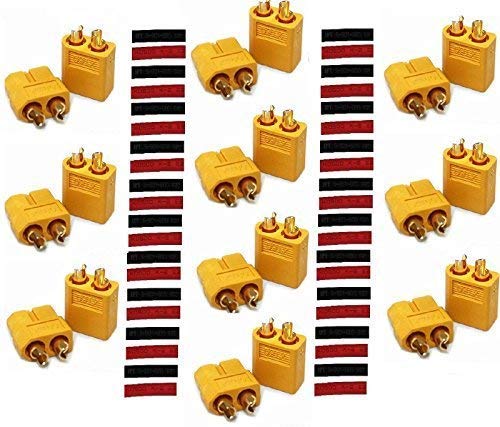
Edit: Also worth noting that the listing for X60 connectors I linked came with red and black heat shrink tubing.
The only video I could find of the MOSFET board installation was very long and somewhat unclear to a newbie. It looks like he mounts it under the printer rather than the control box and overall just seemed really difficult.
I just went ahead and pushed the button on my order from Amazon that includes the XT60 Connectors w/ Heat Shrink and the 6-1 Soldering Kit I would have preferred the MOSFET but in hopes of not getting over my head, it was a total of about 30$ and seems doable.
I tend to use these quite a bit to keep cables bundled together. These are good if you need a bundle of cables protected from a chair, walking, animals. I'll then attach the bundled cables to items/table legs/other cables with these
Both of my cats love twist ties and zip ties. They just aren't an option.
My PC case is a server rack case too, so I have a ton of rack cable organization panels on the back of it rack.
While you are at it, replace the lossy Tamiya connector there. https://www.amazon.com/Finware-Female-Bullet-Connectors-Battery/dp/B01ETROGP4/ref=sr_1_4?keywords=XT60+connectors&qid=1571109188&sr=8-4 wire both ends and you wont need to adapt anymore.
https://www.amazon.com/Finware-Female-Bullet-Connectors-Battery/dp/B01E9HM7NC/ref=sr_1_6?ie=UTF8&qid=1480295788&sr=8-6&keywords=XT60+connector
This is what you're talking about, right? Get a multiple pack, always good to have excess!
Ok thank you so much! Is it these that have been linked from that website?
https://www.amazon.com/Finware-Female-Bullet-Connectors-Battery/dp/B01ETROGP4/ref=sxts_k2p_hero2?pf_rd_m=ATVPDKIKX0DER&pf_rd_p=2668835662&pf_rd_r=S6R4R8BWK779TRY0V987&pd_rd_wg=EO22e&pf_rd_s=desktop-sx-top-slot&pf_rd_t=301&pd_rd_w=5EfKl&pf_rd_i=xt60+connectors&pd_rd_r=P19PEF82ZJTF265YT9T0&ie=UTF8&qid=1478461649&sr=2
pretty sure I got this one https://www.amazon.com/Finware-Female-Bullet-Connectors-Battery/dp/B01ETROGP4/ref=sr_1_4?ie=UTF8&qid=1551117789&sr=8-4&keywords=xt60
​
​
or even something as simple as some wire tubing would clean it up:
https://smile.amazon.com/Monoprice-107118-1-Inch-10-Feet-Flexible/dp/B001114AO4?sa-no-redirect=1
https://www.amazon.com/Outer-Polyethylene-Split-Tubing-Length/dp/B00R1J3546/ref=sr_1_16?ie=UTF8&qid=1524685482&sr=8-16&keywords=Wire+covers
Thank you for the more detailed information. A lot of the explanations that say what to do are always AFTER it's failed, not before. And since I don't know a lot about electrical or boards in general it's all Greek to me.
Before I go breaking my board:
https://www.dropbox.com/s/y6d8at28o7njnjf/2016-09-12%2007.53.17.jpg?dl=0
The issue is with the connector to the left of the one labeled "Power" in my picture above. I need to break the green plastic connector (directly connected to the board) and leave the pins. Then Solder these pins to the posts sticking out the bottom of the XT60 female connectors. Something like: https://www.amazon.com/Finware-Female-Bullet-Connectors-Battery/dp/B01E9HM7NC/ref=sr_1_6?ie=UTF8&qid=1484342494&sr=8-6&keywords=XT60+connector
Then solder the wires to the pins of the male XT60 connector, plug, set it and forget it. Correct?
I can't imagine there being a lot of room from the board to the XT60 connector pins. That's going to be rough for a novice solderer like me. Pre-tinning the pins on the female side will be VERY necessary.