Top products from r/esp8266
We found 42 product mentions on r/esp8266. We ranked the 146 resulting products by number of redditors who mentioned them. Here are the top 20.
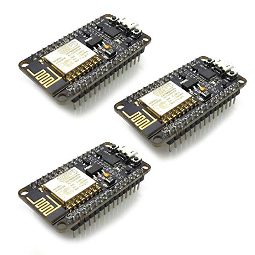
1. HiLetgo 1PC ESP8266 NodeMCU CP2102 ESP-12E Internet WiFi Development Board Open Source Serial Wireless Module Works Great for Arduino IDE/Micropython (Small)
Sentiment score: 2
Number of reviews: 7
ESP8266 CP2102 NodeMCU LUA ESP-12E WIFI Serial Wireless ModuleBuilt-in Micro-USB, with flash and reset switches, easy to programFull I/O port and Wireless 802.11 supported, direct download no need to resetArduino compatible, works great with the latest Arduino IDE/Mongoose IoT/MicropythonData downlo...
 Show Reddit reviews
2. CircuitSetup Solderable Breadboard PCB for Electronics, RaspberryPi, ESP8266, ESP32 Prototyping - with 3.94" x 2.375" x 1.0" (100x60x25mm) Project Box (2 Pack w/ Box)
Sentiment score: 2
Number of reviews: 3
2-pack with project boxesHoles for 2 & 3 pin screw terminals & DC power jack that are connected to power railsAdded holes for flexible configurationsPower rail holes line up with component holesComes with 8 screws
 Show Reddit reviews
3. JBtek Breadboard Power Supply Module 3.3V/5V for Arduino Board Solderless Breadboard
Sentiment score: 1
Number of reviews: 3
Product Name: Breadboard Power Supply Module ; Fit for: MB-102 BreadboardInput Voltage : DC 6.5-12V;Output Voltage : DC 3.3V 5VPackage Content : 1 x JBtek Breadboard Power Supply ModuleOutput Current: 700mA(Max); Total Size : 51 x 32 x 19mm/ 2" x 1.3" x 0.75" (L*W*H)
 Show Reddit reviews
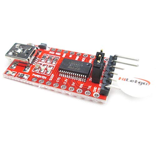
4. HiLetgo FT232RL FTDI Mini USB to TTL Serial Converter Adapter Module 3.3V 5.5V FT232R Breakout FT232RL USB to Serial Mini USB to TTL Adapter Board for Arduino
Sentiment score: 0
Number of reviews: 2
Chipset: FT232RL, not genuine FTDI chip, Working Voltage: 3.3V/5.5VRXD/TXD transceiver communication indicator, with 500MA self-restore FusePin Definition: DTR,RXD,TX,VCC,CTS,GNDSupport Win95/98/98se/ME/2000/XP/win7 32bit 64bit /Vsita/, do not Support Win8Please download the driver and files at link...
 Show Reddit reviews
5. DIYmall 0.96" OLED Module 0.96 inch I2C IIC Serial 128X64 OLED Display Module SSD1306 Driver for Arduino 51 MSP420 STIM32 SCR Raspberry PI (1pc X White)
Sentiment score: 1
Number of reviews: 2
Document link: https://drive.google.com/open?id=1qkexPET5MUICAarGOtlnQk4F-JEKkrHZThe screen is made in Taiwan, quality is much better. Compatible with MMDVM,Pi-Star, and it works with raspberry pi. https://tech.scargill.net/ssd1306-with-python/The IIC address can be changed,it is convenie...
 Show Reddit reviews
6. Icstation 3V 1 Channel Relay Power Switch Module with Optocoupler Opto Isolation High Level Trigger for IOT ESP8266 Development Board (Pack of 5)
Sentiment score: 2
Number of reviews: 2
【Optocoupler Isolator】 3V/3.3V power relay module supports photocoupler isolation control.【High Level Trigger】The relay module is triggered by high level signal, which can be input from microcontroller IO.【Jumper Caps】You are free to select whether the relay and the signal share the same...
 Show Reddit reviews
7. ESP-01S USB to ESP8266 ESP-01S Wireless Wifi Adapter Module Wi-Fi CH340G 4.5-5.5V, 115200 Baud Rate
Sentiment score: 1
Number of reviews: 2
Document link https://tinyurl.com/y2svtas5, The 01S is DOUT protocol, please choose SPI MODE as DOUT when you program itBaud Rate: 115200, Selectable working mode: On-board toggle switch. UART side for serial TTL debugging by AT commands, PROG for firmware programmingUSB to serial TTL chip: CH340G, ...
 Show Reddit reviews
8. MakerFocus 2pcs ESP8266 NodeMCU LUA CP2102 ESP-12E Internet WiFi Development Board Serial Wireless Module Internet for Arduino IDE/Micropython with Free Adapter Board for ESP8266 ESP-01 and nRF24L01+
Sentiment score: 1
Number of reviews: 2
A customer recently sent us an email saying that the product he received was not the ESP8266 but the Mini Nano V3.0. We are very sorry about this! Please don't worry, we will send replacement. If you receive the product is Nano V3.0 ATmega328P, Do not return the wrong product, Please provide your wr...
 Show Reddit reviews
9. diymore USB to Serial ESP8266 ESP-01 Adapter Wireless ESP8266 CH340 WiFi Module
Sentiment score: 1
Number of reviews: 2
Perfect Companion for ESP8266: A USB-to-serial module that converts the USB interface to a serial port suitable for ESP8266.Using CH340 Serial Chip: More stable performance, powerful compatibility, support all Windows system.The main purpose is to connect ESP8266 and computer PC via serial port.Litt...
 Show Reddit reviews
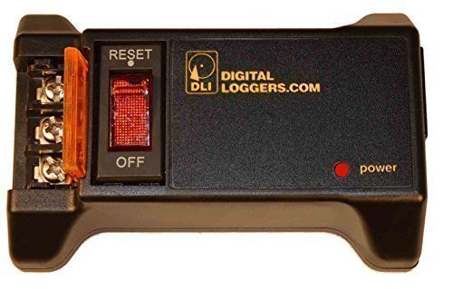
10. Enclosed AC/DC Power Relay with Protection & De-Bounce. Screw Terminals. 120V Trigger Input.
Sentiment score: 2
Number of reviews: 2
Safe and easy to install. Controls any AC or DC device.Durable high current relay for long life and reliable switching.De-bounce circuit for safety. Dry contact relay output - connect to any voltage circuit.Thermal switch and circuit breaker add safety, limiting current to 15 Amps.Includes detachabl...
 Show Reddit reviews
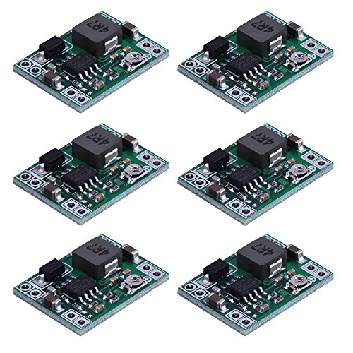
11. eBoot Mini MP1584EN DC-DC Buck Converter Adjustable Power Supply Module 24V to 12V 9V 5V 3V (6 Pack)
Sentiment score: 2
Number of reviews: 2
Mini MP1584EN DC to DC buck converter module with a wide operating rangeInput voltage: 4.5 V to 28 V; Output voltage: 0.8 V to 20 VOutput current: 3 A (maximum); Conversion efficiency: 92% (maximum)Output ripple: less than 30 mV; Switching frequency: 1.5 MHz (highest), typically 1 MHzOperating tempe...
 Show Reddit reviews
12. UTC Fire and Security SM200 Smoke-In-A-Can. Canned Smoke
Sentiment score: -1
Number of reviews: 1
Safe, sure smoke detector testingNon-toxic formula, contains no CFCsEvaporates completelyUL listed for all brands and models of photoelectric or ionization type smoke detectorsAppearance and Odor: Colorless, liquid, alcohol odor
 Show Reddit reviews
13. CR Magnetics CR8410-1000 General Purpose Wire Lead Current Transformer, 2.1 Vmax RMS, 20 A Maximum Input Current
Sentiment score: 0
Number of reviews: 1
Alternating current sensingEpoxy-encapsulated with polypropylene resin caseWire lead connectionUL Recognized and CE certified for quality assurance
 Show Reddit reviews
14. microtivity IM206 6x6x6mm Tact Switch (Pack of 12)
Sentiment score: 1
Number of reviews: 1
A dozen 6x6x6mm micro tact switches for connecting electrical circuits
 Show Reddit reviews
15. Mediabridge USB 2.0 - Micro-USB to USB Cable (6 Feet) - High-Speed A Male to Micro B - (Part# 30-004-06B)
Sentiment score: 0
Number of reviews: 1
FULL USB 2.0 SUPPORT: Sync data at 480 Mpbs. Charge Android / Windows based smartphones, tablets & MP3 players, digital cameras / camcorders & more.FAST: Thicker wire allows for faster charging. Tested to sustain over 2.5 Amps.COMPATIBLE WITH: Smartphones, tablets, MP3 players, cameras, hard drives,...
 Show Reddit reviews
16. First Alert RM4 Smart Relay
Sentiment score: 1
Number of reviews: 1
Activates auxiliary devices when alarm device soundsWorks with compatible BRK and First Alert smoke, heat, and carbon monoxide detectors120V AC poweredEnhances the effectiveness of your detector alarmGreat for adding a strobe light, siren, bell, door closer, or similar deviceFaster turnarounds on jo...
 Show Reddit reviews
17. TP-LINK TL-PoE10R Accessory PoE Splitter IEEE 802.3af
Sentiment score: 1
Number of reviews: 1
TP-Link TL-PoE10R Accessory PoE Splitter IEEE 802.3af Compliant Retail
 Show Reddit reviews
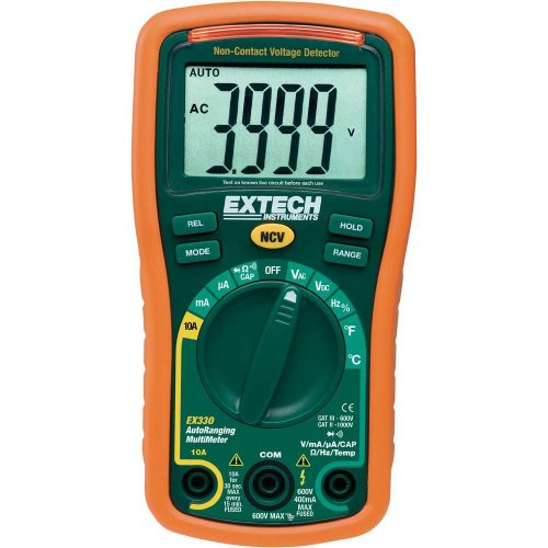
18. Extech EX330 Autoranging Mini Multimeter with NCV and Type K Temperature
Sentiment score: 1
Number of reviews: 1
Built in non-contact AC voltage detector (NCV)Transmitter and Receiver snap together for easy storageCat III 600V UL listedIncludes Type K temperature probeRubber holster protects meter
 Show Reddit reviews
19. First Alert Hardwired Wireless Smoke Alarm with Photoelectric Sensor and Battery Backup, SA521CN-3ST
Sentiment score: 1
Number of reviews: 1
Help keep your family safe with this hardwired smoke alarm that wirelessly interconnects with other First Alert–enabled alarms to create a home safety networkEquipped with photoelectric smoke sensor optimized to detect larger smoke particles produced by smoldering fires; helps minimize the number ...
 Show Reddit reviews
hey, the relay won't work very well if you're using RGB LEDs. One of the coolest features of RGB is the ability to mix colours by pulsing each in sequence for different amounts of time. The relay may not be able to switch fast enough, and you'd need of for each 'colour'.
Personally I don't find the Reddit format to be the best for asking these types of questions, as often the 'popular vote' goes to the answers that are short and easy to understand, which may not be the 'best' answer. I prefer http://www.eevblog.com/forum/index.php and the related electronics vblogs, and https://electronics.stackexchange.com/.
For a great mid-range multimeter I love the Extech EX330 (https://www.amazon.ca/gp/product/B000EX0AE4/ref=oh_aui_search_detailpage?ie=UTF8&psc=1), especially with its built-in non-contact voltage detection for working on household wiring (not related, but it's so handy!). The Fluke 87-V is, in my opinion, the cream of the crop and priced accordingly. There are cheap multimeters for $5 that will get the job done, and I do keep these in my vehicles -- eBay and a month of shipping time works well here. Searching eevblog.com for "shootout" (search Google for "site:eevblog.com shootout") reveals great comparisons, too many to read through but indulge the a bit to get a feel for what to look for.
This is the polar opposite of SMD, but I thought I'd share my solution...
While I love DIY, smoke detectors are important. I wanted to interface with my home system but without compromising the integrity of the system.
Get a 120v first alert.
First Alert SA521CN Wireless Interconnected Hardwired Photoelectric Smoke Alarm with Battery Backup https://www.amazon.com/dp/B000EVO9D4
Get the smart relay interconnect.
BRK RM4 Smart Relay for First Alert https://www.amazon.com/dp/B0039PF21U
This includes schematic for wiring to the detector and the color codes for NO/NC relay connection.
~~Get an optocoupler or isolation relay. Mains Voltage! The output of the RM4 is 120V.
Enclosed AC/DC Power Relay with Protection & De-Bounce. Screw Terminals. 120V Trigger Input. https://www.amazon.com/dp/B017743I7S
The RM4 output powers the relay. The screw terminals connect to the 8266.~~
Get a Esp8266; Flash tasmota firmware. Configure for switch and mqtt. Wire it up.
First Alert is now part of the matrix.
Quick update: Did not need the second relay/optocoupler. The BRK RM4 is an isolated relay. Their docs did not make that perfectly clear so I assumed worst case w/o testing it.
Inspired by /u/commanderkull's post here, I turned an LED-matrix into a performance monitoring tool for my Linux PC. In the gif I am stopping+restarting a Windows VM to show what it looks like when the load changes (of course Windows blue screens, right?)
I wrote a small server to grab the current CPU, memory, and swap usage of my system when the ESP8266 requests it. The ESP8266 then parses the the string and lights the LEDs as necessary.
I have CPU usage displayed in blue LEDs, memory in green, and swap in red. The three colors are added together when displayed (i.e., all the LEDs turn right if each of the above are at 100%)
The code can be found on my GitHub. It's quick and likely dirty, but it gets the job done. The server doesn't cleanly handle the client disconnected+reconnecting right now, but I might add that in the future. As I hinted above, the server only works on Linux right now. Feel free to fork my repo to add Windows support if you like.
This is my first project that I'd consider more or less complete, but it could stand to look a bit nicer. If anyone has any suggestions for that, I'm all ears.
Compnents used:
NodeMCU ESP8266
LED Matrix
Misc. jumper wires
Personally, I'd go with the ESP+Relay. It might not be the simplest way to do this, but it'll be the cheapest and you'll learn more. It'll be easier to implement the DFPlayer into the ESP than it would be to modify the firmware on a Sonoff/Shelly to do it.
You could get something like this TTGO T8 board on Amazon that has a MicroSD slot on board, hook up an I2S amp breakout like this for $6 and playback audio directly from the board.
I spent a long time trying to find ESP resources too, I can't help you breadboard it, but this is what I use for my ESP-01Ss:
https://www.amazon.com/gp/product/B01J2UXXCA/ref=ppx_yo_dt_b_asin_title_o09_s00?ie=UTF8&psc=1
You'll see in the reviews of that item that you need to add a push button to it (literally 2 solder points, and there are pictures)
Something like this would work, you might be able to find cheaper:
https://www.amazon.com/microtivity-IM206-6x6x6mm-Tact-Switch/dp/B004RXKWI6/ref=sr_1_2?keywords=push+button+arduino&qid=1564884279&s=electronics&sr=1-2
Once you have the development board with the push button on it, you put in the ESP-01S, hold down the button while you insert the usb to your PC, then run whatever software you want to write to the esp.
Hope this helps!
Love the push/pull analogy. Thanks for that one, makes sense. Kind of a supply vs demand situation.
Yes, same power supply but only interact via a relay: GPIO2 on ESP-01 goes high (+3.3v, remember I'm still learning terminology here) when triggered via message, opens 3.3v relay (https://amzn.com/B01M0E6SQM) which connects 12v via step-up to gate remote which has it's button locked on. So 5v source split into 3.3v step down and 12v step up, separated by the relay downstream.
The setup allows me to skip two important features: needing to deconstruct/integrate with the remote board to replicate a button press (which would have been destructive) and needing to power off a battery (would have required ongoing replacement & cost).
I agree. I hope they come down a little, but honestly they'll need to drop below the price of a C.H.I.P. ($9) for me to be interested. Considering I pickup Nodemcu boards for $7.50 each, that's a tall order.
hi, sure! I used a cheap generic "Buck Converter DC DC Step Down" referred in the amazon listing as MP1584EN, that takes max 24V IN (so we should be within the range even on charging phase) and lowers it down to 3.3v needed to run safely the esp8266.
amazon link: https://www.amazon.it/gp/product/B01MQGMOKI/ref=ppx_yo_dt_b_asin_title_o01_s00
​
on my module i have a screw for selecting the desired voltage output, you have to be very accurate, slights movements of this screw cause big changes in output, but with some patience and a multimeter you should be able to set it up for your desired OUT value.
​
as for your LDO attempt: i don't know which model you used but if it gets hot it's either too much voltage IN, hence the lowering process produces too much heat or too much amperage to sustain. Check the datasheets if you remember which model you used
Don't. Use something like these.
I'm sure you could find them cheaper on Aliexpress or eBay, but I use these exact ones with NodeMCUs, WeMos D1 Minis, and WeMos D1 Mini Lites all the time. They work great.
For real PoE (and if you already have a PoE switch), you can use a TP-Link splitter at the MCU end. Trust me, 10 quid is cheap compared to some of the "PoE shields" you can find online.
Also noticed this on ebay. Is that an ENC28J60 integrated with an ATMEGA328? Looks cheap and cheerful.
Approved your link from the spamfilter, please just post the relevant part the next time like this:
Link
I've used aliexpress or Amazon depending on how quickly I wanted the things.
For a NodeMCU I'd suggest going with the version 2 instead of the version 3 since they fit better on a 400 point breadboard. I generally just search for 'NodeMCU CP2102' which should get you to the version 2.
That relay is a nice looking device, good find. They also make a cheaper version, http://www.amazon.com/gp/aw/d/B017743I7S/ref=pd_aw_sim_23_of_6?ie=UTF8&dpID=51RYb%2Ba%2BayL&dpSrc=sims&preST=_SL500_SR100%2C64_&refRID=0HWM3SV21K3EEQT2B97X
Get a programmer like this, with the switch on it to make everything easy peasy
https://www.amazon.com/ESP-01S-ESP8266-Wireless-Adapter-4-5-5-5V/dp/B07KF119YB/ref=asc_df_B07KF119YB/
I use one of these as an ESP-01 programmer. Strangely, there is no button on GPIO0 so I had to solder one on--see the pictures in the reviews to see which pins. Simply stick ESP-01 in, hold down the button, plug it in to USB and hit upload. Also watch orientation, I had the ESP-01 backwards first and it got toasty real fast but luckily wasn't damaged.
> https://learn.adafruit.com/adafruit-huzzah-esp8266-breakout/overview
I have the exact board, and I also had issues powering it from a USB port. I'm currently using this power supply and have had 0 issues so far. I highly recommend a supply like this because it easily plugs into a solderless breadboard and can supply both 3.3v and 5v simultaneously. I combined it with this AC adapter. It's 9v, but the voltage regulators on the power supply will burn off the extra voltage as heat.
So now you can omit the voltage wire from the FTDI chip, but you still need a ground wire to go from the FTDI chip to the breadboard's ground.
Also, buy a multimeter if you don't already have one.
Question about the NodeMCU board... I bought this recently and am having an annoying hard time figuring out what the integer values for the pins should be. These boards have pins labeled D0-D8 but using those as pin values in my code doesn't seem to do anything (I have a simple LED connected and am merely trying to make it blink to start with).
Is this board similar to what you used and did you have any issues figuring out pin mappings? Maybe I'm doing something else wrong...
Bought from Amazon, like $8.79, Prime.
https://www.amazon.com/gp/aw/d/B010O1G1ES
Just got it today, and never had it loaded with anything at this point.
I also just ordered 2 more from this one.
https://www.amazon.com/gp/aw/d/B01IK9GEQG
I had seen this one: https://www.amazon.com/gp/aw/d/B01MQGMOKI/ref=sspa_mw_detail_5?ie=UTF8&psc=1
Where they specify that damage could occur if used at less than 10% load (which at a design load of 1 amp an esp8266 would be pulling ~3-6% of an amp most of the time). Unfortunately I just realized that neither of these are what I need as I forgot that my source is 24 vac rather than vdc. I could rectify it but am trying to avoid an having circuits upon circuits in my design atm. Thanks anyway for pointing that one out. that's good info for future projects.
Does your breadboard come with a power supply? If not, this one is good: https://www.amazon.com/dp/B010UJFVTU/ref=cm_sw_r_cp_apa_T-ihzbKYP93BC
It has both a 3.3v and 5v line.
It looks like one of these.
It's a .96" oled display with an i2c interface. The underlying controller is an SSD1306 and by searching for that you can find lots of code for the ESP8266.
> USB uart device
I had to look it up which mean no I am not using a UART device.
I understand the USB device i have with the switch i soldered on there to short out the pins is just for updating firmware so I kind of gave up on that for now as I am literally just trying to get the device to be visible and send AT commands to it, so i thought the stock firmware would allow me to accomplish this.
Since I have not seen the device on my computer I have no idea what firmware is on the device itself.
FTDI: https://www.amazon.com/gp/product/B00IJXZQ7C/ref=oh_aui_detailpage_o01_s00?ie=UTF8&psc=1
The ESP8266-ESP01 I bought from here: https://www.amazon.com/gp/product/B01MT6T73L/ref=oh_aui_detailpage_o05_s01?ie=UTF8&psc=1
Here's the code. I used this for the current transformer. This doesn't have the changes when I added the well pump monitor but the logic is mostly the same.
Mediabridge USB 2.0 - Micro-USB... https://www.amazon.com/dp/B004GF8TIK?ref=ppx_pop_mob_ap_share
what about using a NodeMCU to control a dual relay board?
I have one of these https://www.amazon.com/JBtek-Breadboard-Supply-Arduino-Solderless/dp/B010UJFVTU
Should that work?
Something similar to this one with a mini-usb female on-board. Been around for 3 years.
Here is the fixed link: https://www.amazon.com/dp/B07H9CV1H9/ref=as_li_ss_tl?ie=UTF8&linkCode=sl1&tag=sugarmanparts-20&linkId=2c4a7b3123a4074c83c8782b2ba54adb&language=en_US
https://www.amazon.com/dp/B07H9CV1H9
It's by hiletgo
Thanks for the link. I've read pretty much everything I could find online about this topic in the last several days (which unfortunately isn't a ton) but the main question pertains to using it with the ESP-01S USB to ESP8266 Adapter Module.
Most 3D Printers have Micro USB these days, so my thought process is basically plug ESP8266 -> ESP-01S Adapter -> USB Micro adapter -> 3D Printer board.
Would this sufficiently take the place of soldering to the rx/tx pins on the board? Here is a quick look at the most common method being used right now, but soldering the board is something I want to avoid due to warranty, portability, etc.
You can buy smoke in a can .
Arduino engineers hate him/her due to this one small trick......
I originally had my garage Controller using an Uno that spoke to an esp8266. I found working with the ESPs AT firmware over serial a royal pain in the ass. I have since switched to just using an esp32 (esp8266 would work just the same) instead of the Uno. The esp boards are much more powerful micros and can still be programmed via Uno. Also I didn't need a logic level convertor between the two. I would seriously consider getting One of these for $9 and cut out the uno completely. What took me days to get working on the Uno/esp combo took an hour with the esp alone.