 Reddit reviews Yescom 110V AC 30V 10A DC Power Supply Precision Variable Digital Adjustable w Clip Cable
We found 4 Reddit comments about Yescom 110V AC 30V 10A DC Power Supply Precision Variable Digital Adjustable w Clip Cable. Here are the top ones, ranked by their Reddit score.
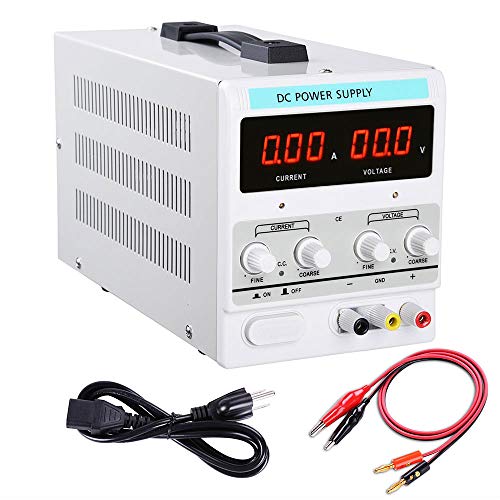
Durable steel caseConstant voltage and constant current operation mode (C.C and C.V. automatic conversion)Multiple protections: over voltage (OVP), open circuit (OCP),over temperature (OTP)Safe circuit design, high quality key components adopted, the power supply can be used in 24 hours with full loadIntelligent temperature control fan adjusts the speed according to the load situation, effectively reduce noise and prolong the life of fan
This is the one I got, unfortunately the price has jumped a bit. Here's another one, though. Should be sufficient
a) If you want to be able to run the three of them at full speed, you need a > 120W power supply (12V3.3A3 = 118.8W) that outputs either fixed 12 V or variable voltage that covers some of the range 0-12. This should be relatively easy to find in a hardware or a circuits store. You could even possibly use a computer PSU with some hacks, assuming the different output support this wattage at 12V.
b) I wouldn't think so. I'm not an electrician but I believe many simple dimmers are mostly inductors or have some internal circuitry to drop the voltage, most of them assuming AC in and AC out which is not your case. You want a DC-DC converter, ideally this is internal to the power supply itself (variable output power supply), there are also relatively simple circuits that do this (look switch mode power supplies, dc/dc converters), or you can go with a simpler (but lossier) solution with an in-series resistors or a number of diodes (ca 0.7-1V drop each), just note that those will simply "burn off" excess voltage, and combined with the amperage you are giving they will produce quite a lot of heat (you'll need high wattage components and heatsinks). Another solution here is a low frequency pulse width modulator (PWM) that alternates between pulses of 12V and 0V, though depending on the internals of the fan this may or may not work.
c) Again the answer here is it depends on the type of fan. So motors like you'll find in fans need some sort of an oscillating circuit to get the fan moving, it's not a simple resistive circuit, if it were, you're assumption about the linear relationship between voltage and current is correct. Most of these fans are designed in such a way as to reduce their speed with lower input voltage, but the exact relationship between voltage, current and the fan RPM is likely nonlinear and fan dependent. Most computer fans for example have 3 pin connectors, with the one pin giving a pulse on each fan rotation (I believe) which is how the motherboard can see how fast it is rotating. This is a form of a feedback mechanism which can be used by a driver circuit to figure out what voltage output is needed to reduce the fan rotation to a certain point (you want a certain RPM, you lower the voltage until you get it).
To summarize, you are probably best off getting a variable voltage power supply, something like this: https://www.amazon.com/Yescom-Precision-Variable-Digital-Adjustable/dp/B00SWK6M0M (note I have no idea about the quality of this model). You can then wire up all the fans in parallel and change the voltage to change the fan speed. Make sure you don't output much more than 12V as you will likely destroy the fans. If you are looking for a more permanent solution you can find some variable power supplies that fit your needs and are less "user interfacy" and more robust to sit and run for extended times.
A bonus of the bench top power supply is that it will be super handy when you start messing around with circuits in general. To understand more I recommend picking up the basics of circuit analysis, e.g. https://www.khanacademy.org/science/electrical-engineering/ee-circuit-analysis-topic (I have not gone through this myself), going to your nearest hardware store, get a breadboard and some components and start playing around.
Yea it’s solid so far. I’m pretty sure it’s made in China, but it’s been ok so far. It only cost 60-70 bucks I forget, and I got beefier cables.
I figured if I had to get a more pricey unit then I would but if this one worked and didn’t crap out I’d be good.
https://www.amazon.com/gp/aw/d/B00SWK6M0M?psc=1&ref=ppx_pop_mob_b_pd_title
adjustable voltage, current limiting power supply is what you want
something like this.. https://www.amazon.com/Yescom-Precision-Variable-Digital-Adjustable/dp/B00SWK6M0M
set the voltage at 17 volts.. set the short circuit current at 1/3 of an amp.. hook it to you deeply or totally discharged battery and walk away for a few days.. the 17 volts at a current limited 1/3 of an amp may Dissolve the sulfate crystals.. i have pulled batteries back from totally dead after being slowly discharged over a month..
marine batteries at least at AZ are less expensive than others.. https://www.autozone.com/miscellaneous-non-automotive/marine-battery?filterByKeyWord=marine+battery&fromString=search&isIgnoreVehicle=false