 Reddit reviews EBOOT 5 Pack Boost Converter Module XL6009 DC to DC 3.0-30 V to 5-35 V Output Voltage Adjustable Step-up Circuit Board (5 Pack)
We found 9 Reddit comments about EBOOT 5 Pack Boost Converter Module XL6009 DC to DC 3.0-30 V to 5-35 V Output Voltage Adjustable Step-up Circuit Board (5 Pack). Here are the top ones, ranked by their Reddit score.
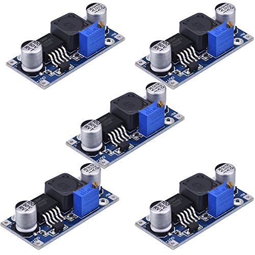
XL6009 DC-DC Adjustable step-up power converter module, the step-up circuit board is a good efficiency non-isolated boost moduleInput: DC 3 V to 30 V, optimum operating voltage range: 5V to 30V; Output: DC 5 V to 35 V voltage is continuously adjustable, maximum output current is 4 AStep-up boost converter module: they can fix on the emergency lamp or other electronic devices between the corresponding voltage range, DIY an output adjustable mobile power, boost charger, etc.DSN6009 is a good-performance 400KHz 4A switch currency step-up boost module; This module XL6009E1 is coming with the 3rd generation high-frequency switch technology as the core chip, the performance is much higher than LM2577Warning: this is only for the increasing output voltage; The input voltage should not be over 30 V to avoid any possible damage
Standard USB power is 5 volts. Your camera needs 7.2 volts to operate. I couldn't find anything manufactured to do this so I put together a step up circuit for my T2i for timelapses and it worked quite well. You're at the whim of whatever quirks the bank and transformer has, so it's not without risk (warranty is likely out the window). I used AmazonBasics' old 16,000mAh power bank, now discontinued, but any USB 3.0 bank *should* work. Tried with another bank and it kept going to sleep between exposures. The step up circuit was similar to these. Just solder the input to a usb cable from your bank, and the out to a camera AC adapter. Gonna need a multimeter while you adjust the pot to get the correct voltage. The tough part is packaging it so the solder joints don't come loose from movement. Let me know if you're interested in this approach and I'll dig it out. Been a while since I've been somewhere worth shooting. Again, I don't recommend it if you want to avoid any risk to your camera.
Hello! I'm currently working on a monitor made from an old screen from an old broken laptop. I've elected not to worry myself with a battery for improved portability (I can do that another time if I want to), but I do want some way to give the screen speakers. However, I also don't want to power those speakers with a separate USB cable and I would prefer to power them using the same cable as the screen: a 12V 3A cable.
For the first version of the speakers, I was going to connect the extracted speakers from the laptop to this 5V powered Amplifier board with a Volume Adjuster and then connect it to this Micro USB-B Breakout Board to enable me to power the speakers using a standard Micro USB-B cable and make the speakers removable in case I want to upgrade them at some point.
My theory for powering them is using a female port for 12V and 3A to take 12V and 3A from the cable and then splitting it into 5V USB output for the speakers and 12V for the control board of the monitor. I was intending on either using two of these Boost Converters, or just one of them and the internals of a Car-USB port.
I'm quite new to electronics though and I'm worried that this won't actually work for some reason that I haven't considered. Could somebody point out any issues they can see with this?
oh dang I actually even had that in my other thread, but I guess I must've not copied it!
I have a boost converter like this one, should that do?
To get longer battery life, can I hook a bunch of charged LiPo cells up in parallel? I've heard of something like, unbalanced cells messing each other up.
> If you have a 33V LED module, a boost converter with adjustable constant current output would give you good smooth dimming.
So let's say I get an LED module like this, with a boost converter like this and appropriate heatsinks. Would this setup work?
I imagine the boost converter is PWM, but I don't know at what voltages this LED module is off, on, and in between. For example, if it turns off at 30V, and fully on at 31V, then I have a very small range to work with and it will be a nightmare to set the potentiometer on the fly. How can I know what would work?
Would one of these work?
https://www.addicore.com/XL6009E1-Boost-Converter-p/ad456.htm
https://www.amazon.com/dp/B00C9179WK/ref=psdc_10967761_t4_B011EBSKK0
https://www.amazon.com/gp/product/B011EBSKK0
https://www.amazon.com/eBoot-Converter-Voltage-Adjustable-Step-up/dp/B06XWSV89D/
Great, thanks.
I do believe that the speed of that fan can be reduced by reducing the voltage.
To reduce the voltage: https://us.reddit.com/r/AskElectronics/wiki/design/power#wiki_reducing_voltage_of_a_power_supply
Buy a ready-made buck converter module:
https://www.amazon.com/Converter-Voltage-Adjustable-Step-up-Circuit/dp/B06XWSV89D/ref=pd_cp_263_2/131-4260846-4210816
Yeah whoops. The one you listed also won't work as it's exclusively a buck converter. That means it can only step down the voltage. I can't quickly find a commercial one that will handle your voltage range. One solution would be to step it up with a boost only converter and then linearly regulate it back down. Here's a boost that could handle it
I don't see an efficiency rating, but something like this would give you a little leeway in terms of voltage. You set the output via potentiometer and it will maintain that voltage (to a within a certain deviation from your input). Max current 4a so you're set there. Your solar panel is pretty low output too so you may be able to get away with running just the voltage regulator, though I really don't know the implications of that.
https://www.amazon.com/dp/B06XWSV89D/?coliid=I394XC9VQT7NWZ&colid=168OCS03SC3LT&psc=0&ref_=lv_ov_lig_dp_it
This one. The component to the left of the out + terminal (Small rectangular chip) is the failure point. (has SS34 on it)
possibly a diode 40V 3A
https://www.digikey.com/product-detail/en/on-semiconductor/SS34/SS34FSCT-ND/2094459