Best electrical motor controls according to redditors
We found 151 Reddit comments discussing the best electrical motor controls. We ranked the 77 resulting products by number of redditors who mentioned them. Here are the top 20.
We found 151 Reddit comments discussing the best electrical motor controls. We ranked the 77 resulting products by number of redditors who mentioned them. Here are the top 20.


0-12v DC speed controller:
https://www.amazon.com/gp/aw/d/B07FLJ6ZHQ?psc=1&ref=ppx_pop_mob_b_asin_title
3-12v DC Adapter:
https://www.amazon.com/gp/aw/d/B013UJAZY8?psc=1&ref=ppx_pop_mob_b_asin_title
100 RPM high-torque DC Motor:
https://www.amazon.com/gp/aw/d/B072R57C56?psc=1&ref=ppx_pop_mob_b_asin_title
I have a 3D printer, so thats what I made all the casing and plastic parts with. Other things I used I had laying around the house like some screws, metal bar for bracing, and a low tension bungee strap.
Full disclosure...I'm not an electrical or mechanical engineer...just a restless new dad that likes to experiment. So, if you do use these parts and/or try to make something like this, please do so at your own discretion.
This is probably your best shot, my guy:
https://www.amazon.com/Stepper-Motor-8-5Nm-Length-Router/dp/B077X9R2CW/
Amazon says it'll ship by Monday. You could even mail it back on Wednesday and probably get your money back if it's undamaged.
Haha it was a pretty simple build. I bought these (https://www.amazon.com/uniquegoods-Digital-Display-Controller-Stepless/dp/B00QLYO7XU) off amazon. All I had to do was build the box, swap out the potentiometer knob with a longer one that would fit correctly for my dimensions, and fire it up. One huge improvement I made to the new one from my old stir plate was using washers to space the magnet from the fan. I found before that the magnet would freeze the fan from spinning unless placed just right.
For sure! The best thing about the Arduino platform how versitile it is.
Do you have any sensors to play with?
I'd recommend buying one of those huge sensor bundles on Amazon or AliExpress and just playing with all of them. [There are tons of them!](
https://www.amazon.com/gp/aw/s/ref=is_s_ss_i_0_11?k=arduino+sensor+kit&sprefix=arduino+sen)
Another really fun thing to build is an obsticle-avoiding rover. You can grab really cheap robot chassis on Amazon along with the Hbridge and sensors.
Here is an awesome cheap chassis with motors and battery box https://www.amazon.com/dp/B01LXY7CM3/ref=cm_sw_r_cp_awdb_7rbszbCNNF6NA
You'll also need an H-Bridge for the motors
https://www.amazon.com/dp/B014KMHSW6/ref=cm_sw_r_cp_awdb_wubszbDX3Y6BR
An ultrasonic sensor for obsticles https://www.amazon.com/dp/B01M13S26V/ref=cm_sw_r_cp_awdb_Jvbszb0HNDB95
You may also want a mini breadboard and a small USB power bank for powering the arduino. (The H-bridge does have a 5v output, but I've never gotten it to work with 4AA batteries.) You could probably splice the 6 volt line from the battery box to the Arduino Vin pin and the H-bridge Vin, but that's up to you.
Most of these things can be found on AliExpress too, if you'd be willing to wait a little longer for cheaper prices.
skip the pid. use an SCR with built in voltmeter. being able to reduce power is important. certainly its worth $25
People will be able to chime in on specific fans but a generic trick with fans to lower the noise is to just run them at a lower voltage.
For 12 volt fans you can pick up a lm2596 buck converter module and dial in the voltage taking fan noise and temperature in to account. They are so cheap that you should buy more than one (they are so cheap because they use a counterfeit chip. I get them for free from Texas Instruments as engineering samples and the price per 10,000 is more expensive direct from TI just for the lm2596 chip itself rather than the whole eBay module in units of one).
https://www.ebay.com/sch/i.html?_from=R40&_trksid=m570.l1313&_nkw=lm2596&_sacat=0
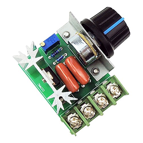
For smaller AC motors/fans you can just use a light dimmer to adjust the speed. Special dimmers are made for this specific purpose (inductive loads).
https://www.amazon.com/KB-Electronics-8811012-Variable-K177-1005/dp/B000F9DAL2/ref=pd_lpo_vtph_60_bs_t_2?_encoding=UTF8&psc=1&refRID=3FG45AKA29Y851BKQ8G4
Also, mechanic isolation of the fan from the bucket/tub will help with noise. Foam rubber tape can be used.
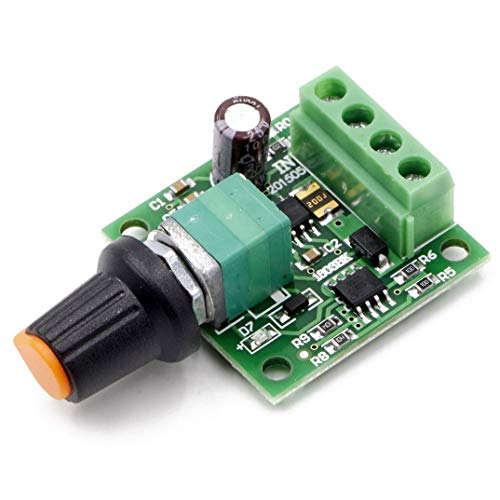
A 12V Power Supply
Simple PC Fan, 12V
PWM Controller
The wall wart will supply 12V with a max of 1A of current. 12V computer fans of that size use at most 0.5A. The PWM controller will control the fan speed. It works by sending out DC pulses, also known as a square wave, of different lengths based on where the knob is set.
To hook up:
There are 4 terminals on the PWM Controller. Look on the bottom to see the polarity. Should be +,- Power and +,- Motor. They're screw terminals so she won't need to solder anything.
Simply hook up the red fan wire to the Motor + terminal, and the black fan wire to the Motor - terminal.
Next, WHILE THE WALL WART IS UNPLUGGED, splice the cable so you have some copper showing at an end. If it has red and black, simply repeat what you did with the fan but use the Power terminals. If the wires are the same color, you can use a multimeter to figure out the polarity.
Schematic
I actually didn't know what I wanted to build first, I'm a software engineer so I was exited to actually write some software and see an object moving hahaha, so eventually a Car came to mind, since it's fun to see it go and move around.
So, to start I looked in amazon for a chassis and wheels and I found this kit that looked pretty simple and functional, so I got that, and then since it only brings 1 motor, I got this to be able to move to the sides, at this point I had no idea how to make that work, but I just figured stuff up on the go, I didn't know how to move the motor so I searched for youtube videos and found out that I needed a motor controller again, amazon was my best friend haha, I also got this battery.
After that I was able to make the Car run, the problem was, I needed some kind of way to guide it, because randomly moving around wasn't that fun, so I came out with the design of the robot looking around I found this module and it was just what I needed, I had a few servos and other components from a mix kit that I got with the Arduino, and I used that (and my girlfriend's help with deciding where to put the pices to make them look nicer) to build the robot that you saw on my first post and then I used this BT module to build the manual mode that you can see in my second post and you know the rest of the story, I'm not sure if I missed something, but let me know and I can answer any question :)
You'll want a motor driver such as this between the motors and the arduino, as the arduino is not equipped to supply the current the motors need.
Already a lot of great answers by clever people here! I can add a bit on motors and electricals, but I also want to say that you're probably underestimating how big a 3' arm is. Imagine that on your desk- it takes up half a table! Sizing the motors for static torque alone doesn't work well, as the inertia at the end effector increases with length^2 which is proportional to dynamic torque, speed, and vibration. Larger limb sections are also heavier and more complicated to make, which makes them even more heavy. Sizing down a little bit will make the arm dramatically more stable and performant.
> Belts or Gears for the actuators?
For 3 lb @ 35" you're looking at a minimum torque of 12.2 N-m at the shoulder. That will require reduction. Belts are far cheaper than gears, especially if you have a 3d printer- plastic pullys work great, although they need to be well glued to metal shafts (NB that a shaft key will greatly reduce strength and durability). Red loctite is great for that. A single belt reduction can do 5x, although you can do 10x+ with idlers. Mcmaster is a good place for belts, but amazon has a small selection that can be cheaper.
Note that belts can be very rigid: highly tensioned, fiber reinforced belts at moderate torque (otherwise the teeth start pulling out) are actually stiffer than most gears, which have a grease film and a gap between teeth that has a slight initial give/backlash. The reason you switch from belts to gears is because you need to tension the belts more tightly for higher torque. Once the tension becomes hard on the bearings and gearbox frame, you switch to gears. Basically you want to avoid gears if at all possible; they're expensive, hard to find, and hard to mount without metal backplates and the ability to cut bearing mounts. SDP/SI is a good place to get gears.
> Once I know how much torque I need, how do I know which type of motor is best for me? Stepper, Servo, Brushless?
Depends how much you want to spend. Hobby servos won't work for a 35" arm, even the $350 dynamixels. You also don't want to be designing your own brushless drivers, and the range of robotics controllers for bldc is limited. You are basically stuck between NEMA 23 and odrive.
NEMA 23 is the cheap choice- you can get very big NEMA 23s on amazon, hook them up to a single-stage 5x reduction, and have gobs of torque and good control. You can even get NEMA 34 for affordable prices. The drivers are stupidly cheap- for <$70 all-in you can have an arduino-controlled joint with 15 N-m of torque and top out solidly over 500 rpm. Add a couple heat sinks and you can increase that a lot- 500+ watts no problem, or 7 watts per dollar.
Downsides are you don't get any regen (not so important on an arm), low/no backdriveability (although this can be nice since the robot usually holds position when it turns off), very loud operation, low efficiency, and pretty low acceleration. Brushless motors require higher reduction and closed loop control, but are quiet, efficient, and can be used to build very responsive + high regen robots. Driving them is the weak link: the 56 V odrive dual driver cost a whopping $150. However for $70-80 per motor you get 40-90 amps continuous for 2 to 5 kilowatts, WITH regen and accuracy to >512 steps. That can be over 20 watts per dollar for the motor, reduction, sensors and driver. The limiting factor is even finding motors that can handle that power.
If your budget is <$500, go for steppers. If it's >$800, I'd go for brushless. You'll get an immense amount of speed and power, both of which are very good for an arm with a 3' reach. Note that 3' is a very large arm- the weight of the arm itself will be very limiting if you don't used fairly sophisticated techniques. 8"-12" sections are a hassle to 3d print. Rotational inertia increases with reach^2 so you'll need quadratically more power for the same acceleration (and to fight wobble). A 26" arm will require only half the power.
> Do I start my design from the end effector or do I start at the base?
I'd start at the end effector- that will set your payload weight and the torque required at the next joint, and so on back to the shoulder. Doing it the other way requires a lot more iteration.
The one thing I always say on posts like this is to learn how to use bearings. Bearings are the #1 cause of wobble in poorly designed arms, and the easiest way to tell if the designer had any clue what they were doing. Use 608 bearings for everything you can. They're incredibly cheap and precise because they're used in skateboards- 20 to 50 cents each. They're deep groove bearings, which are excellent for machinery, and can take 300 lbs radial and 150 lbs axial static load and 2-3x that for dynamic load. They're easily a 50x better value than any other types of bearings. If you want other bearings (maybe very large thin section) go to onlinebearingstore, despite having a 2000s era website/name they're really great. Unrelated, theoringstore is also really great.
The most important thing to know about bearings is that they always, always need a preload. The bearing will not meet specs if it does not have some axial force. It will have a very noticeable play and will wear out quickly. This is why you always use bearings in pairs- not because they can't take it, but because you can't preload a single bearing. You need two bearings to be pressed together. I like disc springs for this, but shims and even just bolts also work well for providing the axial force. You can usually just set your preload by feel (so make it possible to bolt down one bearing closer to the other), but if you want to do the math it's good to aim for an axial force of 50% of the maximum radial force you expect. That can come from static load, or torque from twisting the bearing.
Motor: https://www.amazon.com/HobbyUnlimited-Stepper-Motor-Length-Router/dp/B077X9R2CW
Driver: https://www.digikey.com/product-detail/en/TMC5160-BOB/1460-1250-ND/8440397
The shades are probably over built, after the first set of steppers I tried didn't have enough torque I just said screw out and bought planetary geared steppers, which are a bit pricey.
Nema 17 Geared Stepper Motor Gear Ratio 5:1 3D Printer Extruder Motor DIY CNC Robotics https://www.amazon.com/dp/B00QA5WSDG/ref=cm_sw_r_cp_api_yFTKzbHPVBPDE
SMAKN® TB6600 Upgraded Version 32 Segments 4A 40V 57/86 Stepper Motor Driver https://www.amazon.com/dp/B016ZJS1FA/ref=cm_sw_r_cp_api_uGTKzbJ5XCMGK
HiLetgo New Version NodeMCU LUA WiFi Internet ESP8266 Development https://www.amazon.com/dp/B010O1G1ES/ref=cm_sw_r_cp_api_9GTKzbEZ1TQSP
Outdoor Roller Sun Shade, 6-Feet by 6-Feet, Cabo Sand https://www.amazon.com/dp/B003AU5O2G/ref=cm_sw_r_cp_api_lITKzbW1VKMNA
Here's the post for the pool control stuff:
https://www.reddit.com/r/DIY/comments/6efion/i_built_a_cell_phone_pool_controller_interface/
http://imgur.com/a/qvrCE
> Want to buy some electronics? Cheaper on Amazon
If you're talking about electronic components... they come with no documentation and are likely shit-crap from China.
99% of the time, I can find an American manufacturer that sells better crap than Amazon. Take for instance the L298 H-Bridge. This one from Pololu taking advantage of a TI-chip (DRV8833) is way more efficient (lower Vcesat) AND cheaper than the L298 bridge on Amazon.
The Pololu module has well-written blog-posts as well as American tech support who I can call / email for assistance. American made can be cheaper AND higher quality.
I know some American companies sell high quality stuff on Amazon, but the Amazon market is so flooded with Chinese Alibaba undocumented cheap-crap that they're an awful site for electronics. Most of the cheap sites (Alibaba, Amazon, Ebay) also is well known to hold counterfeit parts.
If you want cheap and don't care much about quality control, you either need to start looking at the branding (there are some high-quality Chinese companies out there) and you need to do your research.
If you're less concerned with quality, Amazon still has inflated prices over dedicated far-east electronics shops like Taydaelectronics.com (which still has to rely on their own branding: so I trust Tayda over most Amazon sellers). Thailand-made, which has better relationship with the US.
What's the goal of the workshop? To introduce programming? To introduce electronics? Does your target audience already have these basics down and you just want to cover some advanced control system topics?
(From experience these things tend to forget scope and leave attendees confused or bored. Or both.)
If budget isn't an issue and you don't want to focus on hardware buy some Pololu 3Pis: Arduino compatible they can work with C, C++, graphical programming and many languages.
Most of the time budget is an issue. If you're EE, take a look at the Harvard AERobot and build a few, they're pretty simple and cheap. (Or buy some: store link) They came from the Afron challenge:
http://robotics-africa.org/2014-design-challenge
No money and PCBs are too much work? Arduino + scrap electronics. CD drives, computer fans, etc. Or try this chassis, use a cheap motor driver design. I've done a similar workshop with cardboard robots, Arduino derivatives, motors pulled from scrap or surplus and simple IR reflectors bought in bulk (TCRT5000 are 10/$1 on ebay). Using a DC motor, a rubber band and food skewers in plastic straws you can make pulley systems that are cheaper than gearboxes. But these are neat. I didn't want programming to be a drag so we used Ardublock.
[Also: your Facebook group is closed, I couldn't see posts to make more accurate recommendations]
The actuator runs off 12V and has internal switches to cut it off at each end.
I'm still working on how to drive it. Right now I have a ATX power supply connected to a breakout to give me different voltages I need in the cab. To drive the motor I use a H-Bridge connected to an Arduino.
Right now my plan for my cab to run Linux and Attract Mode. I can call a script each time I launch a game that sets the monitor orientation. I have a test script that rotates it now, but that's not a usable thing quite yet.
One thing to note is that the actuator I used is heavy-duty and slow. There are faster ones, and this certainly does not have to be heavy duty. It takes very little force to rotate.
every 3d printer on the market uses these same circuits. You'll be fine if you don't scrape the bottom of the barrel on aliexpress. I'd stick to amazon products with high ratings.
since you don't need all the 3d printer bits, I'd go with one of these: https://www.amazon.com/Longruner-Expansion-Stepper-Heatsink-Arduino/dp/B06XJKVLG3
No major strain on the fan, it just lowers the voltage, not perfect but probably not going to set a fire pulling .3a. I use them on my RC cars for LEDs and stuff. This is the one I have used many times on different projects. It takes 12v and lowers it to either 6v or 5v, up to 3a. I had it at 6v first, but I could feel blowback so lowered it to 5v. Works perfect and is whisper quiet.
No cant be used as a speed controller. It's constant output. If you want to adjust speed, you want a PWM like this. That will allow you to adjust the speed. The good thing about PWMs are they dont lower voltage, they lower the pulse width.
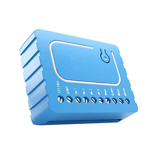
You can install an in-wall dual z-wave relay, like one of these:
I don't know if there are any dual in-wall dimming switches. Personally, I'd rip out the single gang work-box, and put in a old-work double gang work-box.
https://www.amazon.com/Torque-Stepper-Motor-425oz-Router/dp/B00PNEPW4C
I also use zwave. I have one like u/DragonMoose but didn’t like the blue light on the switch and I had to modify the decora switch plate to make it fit. I used this: https://www.amazon.com/Qubino-Z-Wave-Universal-Contact-ZMNHND3/dp/B01MSEG2J1/ref=mp_s_a_1_2?keywords=qubino&amp;qid=1569976896&amp;s=gateway&amp;sr=8-2 for the other fireplace which hides behind the switch which matches all my other switches. I was able to get power from an outlet on the same wall as the fireplace switch on one and from an adjacent switch on the other. Works great but does require zwave hub and not cheap, but relatively easy.
Controlling the flame height is not possible with my fireplaces so don’t know about that unless your fireplace has a control for it. I don’t have a blower in my setup but if you have controls to adjust those, you should be able to automate it.
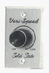
yah you can still buy brand new fan speed controllers that look basically the same
&#x200B;
https://www.amazon.com/KB-Electronics-8811012-Variable-K177-1005/dp/B000F9DAL2/ref=sr_1_8?crid=D14OZQ2Y9WZO&keywords=fan+speed+controller&qid=1571974906&sprefix=fan+speed%2Caps%2C162&sr=8-8
I use these motor drivers with an arduino all the time. Stepper motors are stepper motors - basically read the specs and you'll be happy. Not sure what youre referring to regarding breakout boards.
we are currently using this for our project. It is capable of controlling up to 2 motors but we are just using it to control 1 for now.
The motor is a Nema 17 with 63.7 oz-in of hold torque.
The drive controller doesn't seem like it has the ability to do micro stepping which I didn't see as a problem because the resolution of it is more then i really need already.
Links to both that i got from amazon below.
The application is raising a skylight, which involves the motor turning a hook which grabs the loop to open the skylight.
As far as I can tell it doesn't have to do with resonance but whenever its not actually moving a step its losing all current. This could be my problem as the drive started to over heat when it was not moving. So at the end of the move I disable the driver because the window doesn't need to be held open.
Motor:
https://www.amazon.com/gp/product/B00PNEQI7W/ref=oh_aui_detailpage_o08_s02?ie=UTF8&amp;psc=1
Driver:
https://www.amazon.com/gp/product/B014KMHSW6/ref=oh_aui_detailpage_o08_s01?ie=UTF8&amp;psc=1
I have two 1500w internal, no weld, elements. One is straight plugged in, and the other is on a SCR motor controller with the SCR on a MUCH larger heatsink. 2000w max must mean the damn thing is in chilled oil!! Even at 1500w, at mid-power, the heatsink on it cooks. I would look up even a higher power one, so you are well within the low-mid end of the rating scale.
My boiler is 25l.
Parts list:
Motor and drive train combo: 2 x 550 30000RPM Gearbox with 12V Motor,Electric Motor with Gear Box for Kids Electric Cars and Motorcycles High Speed RS550 Drive Engine Match Children's Ride on Cars https://www.amazon.com/dp/B076Q3XTWB/ref=cm_sw_r_cp_api_i_PiZADbZK937A2
Transmission to wheel adapter: Transmission Gear External Gear Accessories Connect Gearbox Motor and Wheels for Kids Powered Ride-Ons, 550 Gearbox Accessories Kids Ride On Car Replacement Parts E https://www.amazon.com/dp/B076HW2W98/ref=cm_sw_r_cp_api_i_TlZADbWF68M45
Variable speed controller: RioRand 7-80V PWM DC Motor Speed Controller Switch 30A https://www.amazon.com/dp/B071NQ5G71/ref=cm_sw_r_cp_api_i_LjZADbQSB11QY
Connectors: Amass 10 Pair XT60H Bullet Connector Plug Upgrated of XT60 Sheath Female & Male Gold Plated for RC Parts ... https://www.amazon.com/dp/B074PN6N4K/ref=cm_sw_r_cp_api_i_nkZADbG4NVM0E
Spade connectors: Supco T1112 Quick Disconnect, High Temperature, 12-10 Gauge, 1/4" Female Tab (Pack of 15) https://www.amazon.com/dp/B0071NC78C/ref=cm_sw_r_cp_api_i_olZADbX56T2WB
Battery terminal: https://www.ereplacementparts.com/contact-plate-holder-p-154719.html?osCsid=ijjl2im5cg4p7n3dm3k1cbpjv6
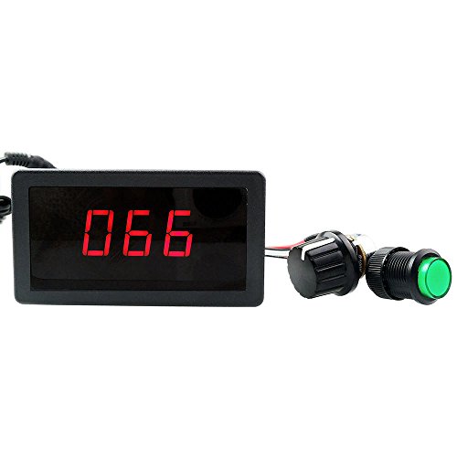
Voltage meter: MICTUNING MIC-VM DC 12V LED... https://www.amazon.com/dp/B078LVLHNF?ref=ppx_pop_mob_ap_share
Note: no affiliate links. All straight links!!!
This all started off with my wife saying that Lightning was a little too slow! I said no problem I got this.
So my first step was to investigate what was the best way to go about this. After a while of researching the best way, I realized that they are more or less oversized versions of my rc cars that I race. With that in mind I was able to do everything.
I started the conversion using just one of the motors. This was so I could make sure I was mentally doing it all right. While the transmission was close to the stock one, it was not a exact fit. I ended up having to trim away some extra plastic and make the opening larger.
Now that the motor and trans is in for the right side I had to start looking at the wiring. The wiring that is in there stock was 18 gauge and while technically will handle the 18v I wanted to be sure we did not melt any wires. I swapped it out one by one using the same 12 gauge wire I use in my RC cars.
The first wires I did was the battery connector. I found the connectors online and used a epoxy putty to make the socket. This ensures the connection is good to the battery.
I then proceeded to replace wires in the harness one by one till they were all replaced. Once it was all setup stock it was time to add in the speed controller. This allows me to turn the speed down (by adjusting the voltage.) I put it online between the battery and the rest of the wire harness. I did it here because it was not able to handle flipping the polarity for reverse. (Popped a fuse finding that out lol. )
Once this was wired up I was able to add in the “fuel gauge”. I put it in what is the “gas cap” on the car. This is a simple dc voltage meter. Nothing fancy here.
Once all that was wired. I needed to make a “Y” splitter for the motors. I know this puts them in parallel all the time and down the road I might change that but for now just forward and reverse was good enough.
Since this car was a single drive motor previously I had to completely make a new hole for this second motor. This was a bit simpler then making room for the first motor.
One thing to note on wiring the second motor. You will want to do it in reverse of the first one as it is spinning the opposite direction of the first motor.
After this was done they only thing I did was relocate the dial for the speed controller from on the speed controller to on the back of the car under the rear fender. This was so I can adjust it without having to remove the seat to adjust it. One thing I may still add is a master power switch. I know this car has one but due to positioning I had to put the battery meter before that switch.
One thing that is still a work in progress is I bought a mltoys brake reduction system. The problem is I was not sure which wire it should go to. This is not the typical plunger switch gas peddle. It is a 6 poll rocker switch. Once they get back to me with that I will get it installed so it is not as jerky on starts and stops.
I think the auber is usually around 80$ or so...you can also buy all in one units from amazon in the 20-40$ range but they dont have cooling fans on their heatsinks...so add an extra 10$ for that.
Attempting to use a resistors to reduce the speed of a DC motor is ineffective. Specifically, it will not stretch the battery life.
The correct way to reduce its speed is by varying the voltage. Use a DC motor controller.
For example: https://www.amazon.com/RioRand-RR-PWM-15V-Voltage-Motor-Controller/dp/B00N30UK2M
Also Qubino (and here) - availability is uneven but it's often discounted. I have a another Qubino relay which works fine.
Yeah, I basically want to have something that can range from 0-100% (or close to it) duty cycle.
This one here says it'll go from 0-100%. And this one says it'll do ~1-100% duty cycle.
Is that a lie? Will it be more like 98% or something?
I'll warn you that even though I bought buttons from the same manufacturer in the same style, he buttons were extremely different brightness. If that happens for you, I used a rheostat to turn down the power to the light.
this is the one i used: https://www.amazon.com/gp/product/B00N30UK2M/ref=ppx_yo_dt_b_asin_title_o00_s00?ie=UTF8&psc=1
This would be our current module of choice from what we understood.
Amazon
We would remove all knobs and switches to plug them directly into the Pi's GPIOs. PWM with the Pi is what the potentiometer does.....right? (please, let this be correct)
No, the adafruit PWM board by itself cannot run a stepper motor. It is only capable of producing the signals to drive a motor controller. You will need it to generate ~8 (depending on phases) high resolution PWM signals to run two stepper motors.
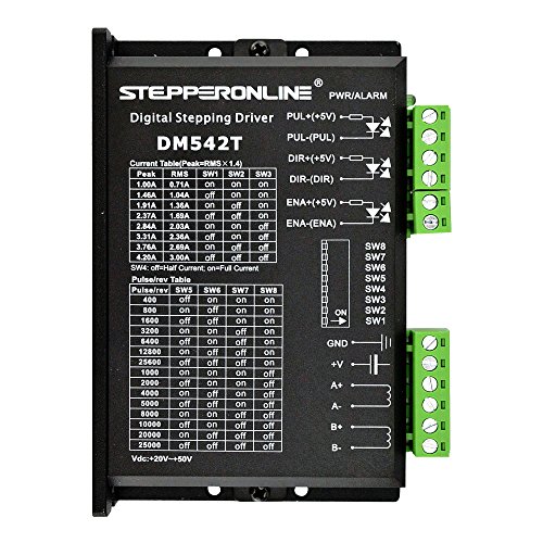
For a best performance setup I would recommend this:
STEPPERONLINE CNC Stepper Motor Driver (1/128 micro step) x2 ~$78https://www.amazon.com/STEPPERONLINE-1-0-4-2A-20-50VDC-Micro-step-Resolutions/dp/B06Y5VPSFN/ref=sr_1_3?keywords=stepper+motor+driver+micro+step&qid=1555450028&s=gateway&sr=8-3
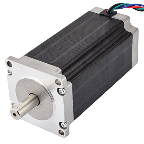
NEMA 23 Stepper Motor x2 ~$160
https://www.amazon.com/MOONS-Stepper-Stepping-Cable01891-ML23HS8P4150/dp/B071YZDMPB/ref=sr_1_2_sspa?keywords=nema+23+stepper+motor&qid=1555450115&s=gateway&sr=8-2-spons&psc=1
There are cheaper ones with less resolution (1/32 microstep) and torque like this x2 = ~ $54https://www.amazon.com/Longruner-Stepper-Printer-Segments-LD09/dp/B07FK8NRKL/ref=sr_1_27?keywords=stepper%2Bmotor%2Bcontroller&qid=1555449504&s=gateway&sr=8-27&th=1
&#x200B;
but moving 15lb with a stepper is solidly moving in on 3D printer / CNChardware territory.
You need to calculate how much rotational torque and holding torque your project needs. Then you will know how much stepper you need. Also how much resolution you are willing to pay for.
Yes the fan A header on the board is software controlled and not really suitable for being used to cool the v6 unless you leave it at always 100%. Wire it to your part fan and you will be fine. Alternatively, if you're lucky and your fan B header works and you can just plug into that instead. I shorted out my fan A header and had to go with wiring in two of these for my cooling needs: https://www.amazon.com/gp/product/B00N30UK2M
I did a similar one recently (with only two switches - no heat) using a https://www.amazon.com/gp/product/B06XFC2V6M/ref=oh_aui_detailpage_o05_s00?ie=UTF8&amp;psc=1 Great product!
Get the one with the zipper chip and heatsink, that looks like this: https://www.amazon.com/Qunqi-Controller-Module-Stepper-Arduino/dp/B014KMHSW6/ref=asc_df_B014KMHSW6/?
You don't need to buy it from this link, tons of places sell them. This is just to show you a photo of what it looks like.
This is the controller that was used https://www.amazon.com/dp/B014KMHSW6/ref=cm_sw_r_cp_apa_i_uvTUCbXP1QBNX
I am using these for a project, and so far I've been really impressed. I don't know the difference between the DQ542MA and DM542T
https://www.amazon.com/gp/product/B06Y5VPSFN/ref=oh_aui_detailpage_o02_s00?ie=UTF8&amp;psc=1
this is a link to the speed controller I purchased
https://www.amazon.com/gp/product/B00QLH8530/ref=oh_aui_detailpage_o01_s02?ie=UTF8&amp;psc=1
It states that it is AC but maybe this is not the proper application.
That's similar to the one I've linked to on Amazon :) just choose the cheaper one or the one with faster shipiing :)
You will need a h-bridge module or some larger transistors/mosfets.
Simplest solution, https://www.amazon.com/gp/aw/d/B014KMHSW6/ref=mp_s_a_1_1?ie=UTF8&amp;qid=1475072347&amp;sr=8-1&amp;pi=SY200_QL40&amp;keywords=h-bridge&amp;dpPl=1&amp;dpID=51o6MdHeT8L&amp;ref=plSrch - 1-2 dollars elsewhere.
http://blog.pixelgiraffe.com/wp-content/uploads/2015/11/roboSketch3b.png (shematic with car kit, dual h-bridge, ultra sonic distance sensor for obstacle avoidance; sensor shield for easier connections)
Do you need to control it with an arduino if your goal is to simply make it go forward?
I am trying to make a small desk fan out of two 12V 80mm computer fans. I am planning to use a DC 12V 1A Power Supply Adapter and just to cut off the end and attach it to this controller. I know the fans require 0.18A each for a total of 0.36. I am planning on simply stripping the ends of the fan wires and twisting them together to feed into the negative and positive motor terminals of the controller. What I am wondering is that if I also take an LED strip and power it from the motor terminal of the controller, will the LED strips still work fine when I twist the knob on the controller to change fan speed? Also, are there LED strips that don't require more than 0.64 amps?
PWM'ing and swapping polarity is bad news for trains with onboard control computers, but I might not fully understand the setup you're describing.
This will work for any system that uses two rails to power a motor. I'm sure there are some exceptions out there but any model train that runs when you put DC voltage across its wheels is probably a good fit.
FWIW here's the H-Bridge I bought. http://www.amazon.com/gp/product/B00CAG6GX2/ref=oh_aui_detailpage_o02_s00?ie=UTF8&amp;psc=1
That's absolutely perfect. Just ordered the 4x4. Thanks. That's exactly what I was looking for-- but all my Google searching should have (but didn't) include 'ball bearing.'
To that end: since I've never built a geared assembly before, I was going to try using a worm gear stepper drive, namely, this one (since I want high torque at the expense of speed):
https://www.amazon.com/gp/product/B073S5GM6Q/ref=crt_ewc_title_dp_2?ie=UTF8&psc=1&smid=A36ZH2MCHPKXUA
connected to and driven by this:
https://www.amazon.com/gp/product/B014KMHSW6/ref=crt_ewc_title_dp_6?ie=UTF8&psc=1&smid=A12MRQC2NA7LMA
What do you think?
What I would recommend is to pick up a 5x7 LED dot matrix display to play with while you wait for the flip dot display to show up. It doesn't look like Adafruit or Sparkfun stock any but here is one currently in stock on Amazon: http://amzn.to/1U2RuhC
The benefit of a LED matrix is that it will allow you to setup a lot of your main code while not having to worry about how to power the actual flip dot display. Once you have your code working to control the LED matrix, making the jump to the flip matrix should be very simple :)
In regards to actually powering the coils, I can't say I have experience with working with these however from my understanding you will most likely need to fabricate a custom controller as you need to have the ability to flip the polarity on each dot to flip the actual dot! The easiest way to do this would actually be to use an H-bridge or motor driver. To continue with the amazon fashion, here is a simple breakout that would be able to control 2 of the dots: http://amzn.to/1UJXb2S
If you have any questions let me know!
EDIT:
I realized I didn't explain why you need the motor drivers to control this. Each little flip dot can actually be thought of as a small little solenoid such that when you apply a DC voltage in one direction the dot will flip one way, when you apply the opposite DC voltage the dot will flip the other way. This is achieved using an inductive device, which can cause extremely high current spikes which will damage any microcontiolller pin directly connected.
The motor driver IC/module is designed to drive these inductive loads, however a little care still needs to be taken make sure that you do not damage the flip dot display or motor drivers. When flipping a dot, it is important to note that you should not constantly apply a voltage but rather just send a pulse long enough for the dot to flip. If a constant voltage is applied it can cause either the flip dot or driver to heatup which is what would in turn cause damage to either of these parts - not good!
Here is the link for my driver:
https://www.amazon.com/gp/product/B06Y5VPSFN/ref=oh_aui_detailpage_o01_s00?ie=UTF8&psc=1
Also the power supply is 2.4A. Assuming A is amp
So a single step is fine, it's just microstepping that's the problem with respect to torque? Or do I have that wrong?
I'm looking at, say, this now, and it claims 0.067 degrees/step. So, that means that it would deliver a decent bit of its rated torque and only move .067 degrees if moved one step? Or should I be looking for an even bigger gear reduction to get that kind of behavior?
I can send a link to the pwm* I am using it’s a simple unit sends the full 18v but turns it on and off at veering intervals per second to regulate power out put also they tend to fail and go full throttle sort of speak so put a kill switch and make sure tiny knows how to use it
RioRand 7-80V PWM DC Motor Speed... https://www.amazon.com/dp/B071NQ5G71?ref=ppx_pop_mob_ap_share
Would a few L298Ns work ? https://www.amazon.com/dp/B014KMHSW6
Or a featherwing.
https://www.adafruit.com/product/2927
These guys from Steppers Online: https://www.amazon.com/Stepper-2-83Nm-8-wire-6-35mm-Router/dp/B00Q62MBHQ
The DRV8825's are rated up to 2.2 amps/coil. I trimmed the pots to feed the stepper 2 amps per coil (bipolar serial). The DRV8825's have heat sinks and I have a 40mm fan with forced air. They get warm to the touch but not hot enough to burn. Holding torque does not appear to be the issue: whenever I'm worried that the axis feels to stiff I hang a 5lb weight off the handle of the handwheel and gravity moves the axis no problem (aprox. 160 oz-in)
Qubino makes one, as well as Fibaro
Maybe someone here knows a bit more about electrical work, but could these work together or do you just use one? Originally I thought forward and back was sufficient, but I might want to work my way up to 23RPM than to start with it. With that amount of torque, I don't know if its going to stall, I think it's going to break something else.
https://www.amazon.com/RioRand-7-80V-Motor-Controller-Switch/dp/B071NQ5G71
https://www.amazon.com/Twidec-Illuminated-Toggle%EF%BC%88Quality-Assurance-Years%EF%BC%89KCD2-201N-R/dp/B07MV5LBX8
> pulse width modulation, look for a PWM DC motor control
Oh Crikey! I've got one of those around here somewhere.
EDIT: Found it. Whoo-hoo! Thanks for the answer! This is what mine looks like: https://www.amazon.com/RioRand-7-80V-Motor-Controller-Switch/dp/B071NQ5G71/
I would look up a CNC router Shield... for $30 CND you can buy a shield and an Uno that works with it.
https://www.amazon.ca/Longruner-Expansion-Stepper-Heatsink-Arduino/dp/B06XJKVLG3/ref=sr_1_fkmr0_1?ie=UTF8&amp;qid=1517498859&amp;sr=8-1-fkmr0&amp;keywords=cnc+router+shield
BEMONOC High Torque Dc 12v Low Speed 2RPM Reversible Worm Gear Motor of Miniature Metal Motor with Shaft 6mm https://www.amazon.com/dp/B01D14QPV4/ref=cm_sw_r_cp_api_i_-azFDbBQFRPM6
Qunqi L298N Motor Drive Controller Board Module Dual H Bridge DC Stepper For Arduino https://www.amazon.com/dp/B014KMHSW6/ref=cm_sw_r_cp_api_i_efzFDb3CHE112
I have had to do this process for many steppers, so I will try to help you out.
You may have to switch the input wires around till they are in the correct order, but this should get you started.
These are what I have:
https://www.amazon.com/Torque-Stepper-Motor-425oz-Router/dp/B00PNEPW4C/ref=pd_cp_60_4?_encoding=UTF8&amp;pd_rd_i=B00PNEPW4C&amp;pd_rd_r=35Y9S4KD82HKA5H9YX3A&amp;pd_rd_w=0KHvJ&amp;pd_rd_wg=Iq2NL&amp;psc=1&amp;refRID=35Y9S4KD82HKA5H9YX3A
This is what you may be talking about:
https://www.amazon.com/Stepper-Motor-Bipolar-269oz-Router/dp/B00PNEPI0A/ref=pd_sim_469_4?_encoding=UTF8&amp;pd_rd_i=B00PNEPI0A&amp;pd_rd_r=61V9SWJJ3XHTTDF9QDE8&amp;pd_rd_w=1Fgkr&amp;pd_rd_wg=kmipE&amp;psc=1&amp;refRID=61V9SWJJ3XHTTDF9QDE8
Longer Length = More torque = Wider shaft needed
It's unlikely that I'd need to go above 350 F, even then, that's pretty high. I'll be using it to run extraction experiments, and my primary solvents have a boiling point between 150-175F so my normal operating temperature won't be above 200F.
However, those heating elements get wicked hot, hot enough for the stainless casing to grow bright red. I wired up a voltage regulator in addition to my PID so the heating elements don't have to run at full blast, but I'd like to be able to run them on high if need be.
Ohh and I'm using an external temperature probe, so my temp readings will be based off the temp of my solution, not the plate.
Have you considered using geared steppers? You'd get finer control and more holding torque.
https://www.amazon.com/Nema-Geared-Stepper-Motor-Ratio/dp/B00QA5WSDG/ref=sr_1_3?s=industrial&amp;ie=UTF8&amp;qid=1539723519&amp;sr=1-3&amp;keywords=geared+stepper
Yes!
Raspberry Pi
[RC-CAR] (http://www.toysrus.com/product/index.jsp?productId=11592253&amp;camp=PLAPPCG-_-PID10226513:TRUS&amp;cagpspn=plat_10226513&amp;eESource=CAPLA_DF:11592253:TRUS) I would NEVER spend 40 on this, My wife got it for 15 at target.
Blue Tooth Adapter
WiiMote
Dual H Bridge
These are the major components and there are a few Misc Components needed.
I have the raspberry pi 2 starter kit, so I used some spacers to connection the Dual H bridge to the top of the raspberry pi case.
You'll also need
Power Supply for PI
Power Supply for Dual H Bridge ( I use 11.1 3S poly battery)
Female to Female jumper wires
Any other questions I can go into as much detail as you want.
Here are two I found on Amazon...have never used them:
https://www.amazon.com/Wireless-Z-Wave-Multi-Input-Output-Contact/dp/B00B6RZ7MM/ref=sr_1_1?ie=UTF8&amp;qid=1540992794&amp;sr=8-1&amp;keywords=z-wave+relay+dry+contact
https://www.amazon.com/Qubino-Z-Wave-Contact-Module-ZMNHND3/dp/B01MSEG2J1/ref=sr_1_2?ie=UTF8&amp;qid=1540992794&amp;sr=8-2&amp;keywords=z-wave%2Brelay%2Bdry%2Bcontact&amp;th=1
I'm going to put the links in a comment, I think they caused my post to get removed due to spam filter earlier:
Don't necessarily have to use Amazon, but I'd prefer a US based company.
Thanks!
You could use a PWM motor speed controller like this to fine tune the power and speed of the motor.
Thank you so much! This is very useful information. My plan was to use one of the following 2 z-wave controllers, but whether I can use 1 or if I"ll need more will depend on the actual power requirements of these strips.
Fibaro
Qubino
I'm going to email the seller to see if they can clarify the power information.
edit: The seller responded and they said 85 watts is correct. Ultimately doesn't matter since I overlooked the fact that they are not outdoor rated! Any recommendation for quality affordable strip lights? I'm looking at something like this now.
LEDENET RGBW
Check this out at Amazon.com
KB Electronics 8811012 Solid State Variable Speed AC Electric Motor Control, 5.0 Max amp, 115V, # K177-1005 https://www.amazon.com/dp/B000F9DAL2/ref=cm_sw_r_sms_apa_i_AVGODbJV6B4AY
Thanks!
I have n channel that will do for now, but ideally I would like a smoother on/off transition. Do you have any links for self contained modules or is this something I need to make myself?
I would be looking to deliver 2-10amps voltages under 20.
Update
I was looking at the following for starters. I can hook up my generator and PSU to it
https://www.amazon.com/Qunqi-Controller-Module-Stepper-Arduino/dp/B014KMHSW6/ref=mp_s_a_1_10?keywords=h+bridge+module&amp;qid=1570973047&amp;sprefix=h+bridge&amp;sr=8-10#
From the product description...
> Operating voltage: DC 0.5-3V; Rated voltage: DC 3V
So unlimited 9V is too much. Try a motor controller like this one.
Beware these are crappy motors, so don't expect much in the way of performance from them.
Just grab a DC motor and something like this, wire together and figure out a face plate.
If you have access to a machine shop that will help a lot. If not you'll have to hack things together.
I'm looking for the stepper motor which can make one revolution in the shortest amount of time possible. In other words, something which can make a catapulting motion. Should I be looking for high torque motors?
I found this one but I'm not sure if it has the right specs for what I'm looking for... Could anybody advise? Thanks!
I've used these two
Qianson 360W 30A DC 12V 3-Phase Brushless Motor Speed Control PWM Controller Driver https://www.amazon.com/dp/B01IEHX12E/ref=cm_sw_r_cp_apa_i_onMVDbMEZHD76
DC 5V-36V 15A 3-Phase Brushless Motor Speed Controller Motor Control Board CW CCW Reversible Switch Motor Driver Control Regulator Module https://www.amazon.com/dp/B078T8YPGG/ref=cm_sw_r_cp_apa_i_2nMVDbZ3022QM
Thanks, am I supposed to invert the logic for the virtual endstops too? I haven't calibrated the steps/mm quite yet.
I can't even get my extruder motor to spin. I've tried adjusting my stepper to give it more amperage, but no luck. Do you know if it can put out enough to move one of these?
This is what they are referring to:
https://www.amazon.com/KB-Electronics-8811012-Variable-K177-1005/dp/B000F9DAL2
Your way it will run at full speed all the time, and be extremely noisy. The switch will allow you to control it so it removes the fumes without deafening you at the same time.