Best automotive power relays according to redditors
We found 56 Reddit comments discussing the best automotive power relays. We ranked the 17 resulting products by number of redditors who mentioned them. Here are the top 20.
We found 56 Reddit comments discussing the best automotive power relays. We ranked the 17 resulting products by number of redditors who mentioned them. Here are the top 20.


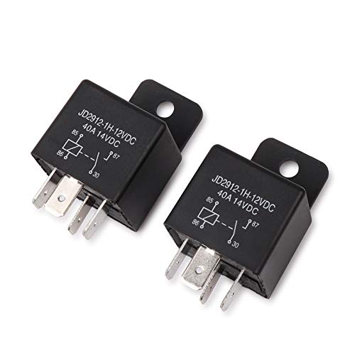


you can do this with a relay and an automotive realy will easly handel 20~30 amps.
A relay is a voltage controlled switch. It's made of a coil, when the coil has current flowing through it turns into an electromagnet. This magnate will pull on the second part, a switch.
The simplest form of the switch will have only two terminals.
When the coil is energized, it will connect the switch together. The second form of the switch will have three terminals. One common connection to two switches. The first switch behaves like described above, Second switch will be connected when the coil is not energized and will break when the coil is energized.
For your circuit, you can ignore the second switch if the relay you get has one.
What you want: 1 relay and 1 pushbutton. Lets use this relay since the pins are numbered: https://www.amazon.com/dp/B01J53IH5M/ref=sxbs_sxwds-stvpv2_1?pf_rd_m=ATVPDKIKX0DER&pf_rd_p=6375e697-f226-4dbd-a63a-5ec697811ee1&pd_rd_wg=fygzA&pf_rd_r=AYHNZ32STPQJA4SSYX5Q&pf_rd_s=desktop-sx-bottom-slot&pf_rd_t=301&pd_rd_i=B01J53IH5M&pd_rd_w=ZBuoO&pf_rd_i=automotive+relay&pd_rd_r=ca1298c0-e1bb-467d-9941-d8e4583b3d44&ie=UTF8&qid=1538503761&sr=1
Pin 86 goes to ground. The pushbutton on one side is tied to you ACC power. Other side to pin 85. Pin 30 gets tied to ACC power. Pin 87 is your output, tie this to the RMT / remote line of the amp. So far, when you push the button, the amp will turn on but when you stop pushing the button, the amp will turn off.
Now the magic. Tie pin 87 to 85.
When you run on the car, nothing is powering the relay coil, amp is off. Press the button that will close the relay turning on the amp. BUT also will power the coil when you let go of the button. The relay will turn off when the key in the ignition turns off ACC power.
All I needed to do after converting my battery voltage to 12 volts was wire up a few switches and a blinker relay. Here is the tail light and blinker relay
Taillight: Greenclick 40W Motorcycle Tail... https://www.amazon.com/dp/B072Q5MK75?ref=ppx_pop_mob_ap_share
Blinker relay: AUDEW 2-Pin Electronic Turn... https://www.amazon.com/dp/B011BTMDQM?ref=ppx_pop_mob_ap_share
Ink bird 12v digital and 100amp relay found on amazon/ebay
https://www.amazon.com/Inkbird-All-Purpose-Temperature-Controller-Fahrenheit/dp/B00OXPE8U6/ref=sr_1_1?ie=UTF8&qid=1484277440&sr=8-1&keywords=inkbird+thermo
https://www.amazon.com/Support-Heavy-Split-Charge-Relay/dp/B012N09BFE/ref=sr_1_1?ie=UTF8&qid=1484277516&sr=8-1&keywords=12v+100+amp+relay
This is the polar opposite of SMD, but I thought I'd share my solution...
While I love DIY, smoke detectors are important. I wanted to interface with my home system but without compromising the integrity of the system.
Get a 120v first alert.
First Alert SA521CN Wireless Interconnected Hardwired Photoelectric Smoke Alarm with Battery Backup https://www.amazon.com/dp/B000EVO9D4
Get the smart relay interconnect.
BRK RM4 Smart Relay for First Alert https://www.amazon.com/dp/B0039PF21U
This includes schematic for wiring to the detector and the color codes for NO/NC relay connection.
~~Get an optocoupler or isolation relay. Mains Voltage! The output of the RM4 is 120V.
Enclosed AC/DC Power Relay with Protection & De-Bounce. Screw Terminals. 120V Trigger Input. https://www.amazon.com/dp/B017743I7S
The RM4 output powers the relay. The screw terminals connect to the 8266.~~
Get a Esp8266; Flash tasmota firmware. Configure for switch and mqtt. Wire it up.
First Alert is now part of the matrix.
Quick update: Did not need the second relay/optocoupler. The BRK RM4 is an isolated relay. Their docs did not make that perfectly clear so I assumed worst case w/o testing it.
Chris Fix has a great video that walks through all of the processes that have to work to generate heat. Good watch.
Edit: I saw this below from /r/shibathedog Maybe it's the relay?
I don't know how to test the switch or the relay.
Try new relay. Just switched mine and it worked. If it's 2 prong try this one:
AUDEW 2-Pin Electronic Turn Signal Flasher Relay Fix Motorcycle Turn Signal Hyper Flash https://www.amazon.com/dp/B011BTMDQM/ref=cm_sw_r_cp_apa_i_hl0KDbNXGA6KB
You need to replace the flasher unit with a led one. I got mine on Amazon {https://www.amazon.com/gp/product/B011BTMDQM/ref=oh_aui_detailpage_o02_s00?ie=UTF8&psc=1}
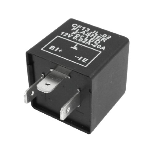
Don't install resistors, this is how people set cars on fire. Instead get an [LED Flasher Relay] (http://www.amazon.com/uxcell%C2%AE-Vehicle-Blinker-Flasher-0-02-20A/dp/B00BLZ9XQK/ref=sr_1_1?ie=UTF8&qid=1463067876&sr=8-1&keywords=led+flasher+relay) this solves the problem at the source and doesn't require any modification of the factory loom.
Do you have a cable box or any other device that makes heat 24/7? If so, you might consider wiring up the fans to run 24/7. That's also the simplest way to wire them. Lower temperatures are good for electronic longevity. Fans wear out in a few years, but are cheap to replace compared to a PS4 or receiver.
If you want to trigger them off your receiver, that's pretty easy to do. Most likely your receiver can't power the fans directly (most 12V trigger outputs are 200-500mA output). Some receivers have a switched 120V outlet on the back, which makes this really easy, you just plug the fans in.
Fans can draw anywhere from 160mA (0.16A) to 600mA+ (0.6A)
The Antec fan you linked doesn't have a spec listed for power draw, but typically very quiet fans are below 300 mA.
If your total fan power draw (add together all fans) is less than 90% of the power your receiver can output, you can hook the fans up directly.
If your total power draw exceeds 90% of the rated output of your receiver, you need to use a relay to power the fans.
Here is a relay board that will work.
Here is the same thing but shipped free (probably from China, may be slow)
You'd also need a 12V power supply that provides enough current to run all your fans together.
Here are USB Fans - plug straight into PS4 or TV, and they turn on when the device powers up.
You could also use a 5V relay to control 12V fans from the PS4 usb if you wanted. Or use the TV's USB to trigger the fans whenever the TV is on.
Here is a plug and play thermally controlled fan setup
I'd plan on using both fans as exhaust on the top shelf. Just make air inlet holes in the bottom. Typically you want 30%-50% more inlet volume than outlet volume if you can get it. Remember all the cracks along the doors and edges will let air in as well. Making an air path across the front of the shelf by trimming is a fine idea.
So, step 1, decide when you need the cooling system to turn on - PS4, receiver, tv, 24/7, or other (such as temperature).
Then I can tell you how to use that device to turn it on.
Does this work as a battery isolator?
https://www.amazon.com/gp/product/B00WMBV05Y/ref=oh_aui_detailpage_o02_s00?ie=UTF8&psc=1
What is the advantage of a more expensive device over this simple relay?
It was really easy since there is a 110 outlet under my fireplace. I used the relay below to trigger the switch and a TP-link smart plug. It was simple to hook up.
https://www.amazon.com/gp/product/B017743I7S/ref=oh_aui_detailpage_o01_s00?ie=UTF8&psc=1
Ok well nice job deleting as much as you can it's very necessary on these bikes. Do you have a manual? I ha e a copy of a minimal wiring diagram I used on mine I can forward to you so you can trace your own wiring. Have you tested the LEDs? Most of these old bikes can't read a signal that small and need a relay (ex:AUDEW 2-Pin Electronic Turn Signal Flasher Relay Fix Motorcycle Turn Signal Hyper Flash https://www.amazon.com/dp/B011BTMDQM/ref=cm_sw_r_cp_apa_KmirzbTJDKYAQ)
With a 6.5 gallon tank it would be sad to only take advantage of 70 miles at a time.... Lol
Get yourself a Voltmeter and test the resistance on the ignition pack, THE STATOR (in case you were unaware... Stator is:the stationary portion of an electric generator. It's under the right side cover. Replacements are not easy to find...trust me...) you're actually at an advantage with no wiring on these bikes. The 80s Japanese bikes were notorious for tons of wiring for no reason.)
I don't know how proficient you are mechanically and I don't want to suggest something crazy and out of you're league... But look at this https://youtu.be/nFAnxpPOlnU
Wish I had a picture of when it was finished but I can't seem to find one... Here was my 80' xs850 http://i.imgur.com/TPY4UMy.jpg
IMO, being a professional 12v installer, a simple relay rated for your application is the easiest, safest way to accomplish what you're trying to do.
terminal 86 to ground, 85 to a switched ignition 12v power source, and the two other terminals connect one battery bank to the other.
This is a proven setup up for years on cars with hydraulics or demanding audio systems where multiple batteries are installed in a particular vehicle.
I just put lights on my drive.
I used this on the front and this on the rear.
Since the motorcycle taillight has a circuit for both the tail light and brake light, I wired the tail light to the same switch as the head light. I bought an adjustable motorcycle led flasher and put the brake light on a second circuit and switch.
So, I ended up with a headlight/taillight combo on one switch, and a brighter, flashing taillight on the other switch. Both of these circuits are only active when the key is turned on. I am quite pleased with the outcome.
While I was in the dash, I also added a 12 volt power port for charging phones and my bluetooth speaker, which has a mount on the dash.
FYI, there is a factory power harness which has unused 12 volt power located behind the key switch.
I'll try to post pics when my phone is charged.
Feel free to ask any questions. I'm pretty familiar with the electrical on the drive now (mine is gas).
Edit: Here are some pics. Excuse the dirty cart. Believe it or not, that little cheapo light bar actually put out too much light. At first, it would light up a stop sign 150 yards down my street. I aimed it at the ground to keep from blinding oncoming traffic.
I have a gas fireplace that was controlled by a switch on the wall. The switch was a low voltage switch that essentially just connected two wires together to turn on the fireplace and disconnected them to turn off the fireplace. The electronics that control the fireplace are behind a panel underneath the fireplace, and there is a decent amount of room and a power strip in there. I believe most gas fireplaces controlled by a switch on the wall have a similar setup.
So what I did was plugged in a Lutron Lamp smart plug (https://www.amazon.com/Lutron-Wireless-Lighting-PD-3PCL-WH-Assistant/dp/B00KHSXB60/ref=mp_s_a_1_3?keywords=lutron+lamp+dimmer&qid=1564055576&s=gateway&sprefix=lutron+lamp+&sr=8-3) to the power strip below the fireplace, and then I plugged in this AC/DC relay to that (https://www.amazon.com/gp/aw/d/B017743I7S?psc=1&ref=ppx_pop_mob_b_asin_title). What the relay does is just make a connection between its terminals whenever the outlet it’s plugged into (the Lutron Lamp plug in this case) is turned on. I then spliced the wires going to the switch on the wall and connected them to the relay. Then, the last step was to pair a Lutron Pico remote / switch (https://www.amazon.com/gp/aw/d/B00KLAXOE8?psc=1&ref=ppx_pop_mob_b_asin_title) to the Lutron lamp plug, and then I replaced the switch on the wall with the Lutron Pico switch. Now I can turn the fireplace off and on from a switch on the wall still, but I can also control the fireplace from HomeKit, Google Home, Alexa, etc. I also set up some rules to automatically turn off the fireplace if it’s been on for 3 hours, and to notify me if it turns on and I’m not home. These are just in case we accidentally hit the button to turn it on while we’re in bed or away or whatever.
Thanks! I'm in Los Angeles, only electronic components place I can think of is Fry's Electronics: www.frys.com
Would something like this work? https://www.amazon.com/SMAKN%C2%AE-SRD-12VDC-SL-C-Channel-Level-Module/dp/B00MMW0XWY/ref=pd_sim_60_3?ie=UTF8&psc=1&refRID=VZ0TCJ9326VS28VJSDEJ
Thanks again for your help.
As long as the circuit is closed, does it matter how it got closed? Meaning, you can use any I/O module to complete the circuit and then hook up a Homekit switch to trigger the I/O module to close the circuit.
For instance, if you used something like this and connect one end to your fireplace (and I'm just using this module as an example as I don't know if it is compatible with your fireplace): https://www.amazon.com/Enclosed-AC-Protection-Bounce-Terminals/dp/B017743I7S/
and the other end to a Homekit switch or outlet. That should work, should it not ?
I'm still in the middle of adding a filament sensor to my OctoPrint setup so I may be missing something, but I think you should be able to use that plugin to achieve pausing a print when the power disappears. The 'Filament Sensor Reloaded' plugin just looks at a GPIO line that you select to determine if filament is present or missing and you can pause the print. If you connect the GPIO to a voltage from the same source as the printer, then you can detect the power removed from the printer and pause. A simple way to do that would be a USB power adapter with a voltage divider from 5V to 3.3V or you could use this power detector - https://www.amazon.com/Enclosed-AC-Protection-Bounce-Terminals/dp/B017743I7S/ref=sr_1_6?ie=UTF8&qid=1506368549&sr=8-6&keywords=iot+relay#Ask
For $9, I'd probably buy the power detector.
Like I said, I haven't experimented with OctoPrint pausing yet, but I would expect the same behavior as pressing the pause button.
It's good but not great. My riding buddy says daylight visibility is ok, but to my eyes it seems a bit dim. That being said I've had several cops behind me and no issues to date.
Functionally it's been perfect except for having to redrill the plate mounting holes. As I'm sure you know it requires an LED compatible blinker relay. Another $7 Amazon purchase. Adjustable Blinker Relay
Future... I'll replace it with something brighter and more integrated. I've toyed with the thought of embedding it into a custom seat pan but it still won't be as bright as I'd like.
I use a Koogeek switch with this relay plugged in:
Enclosed AC/DC Power Relay with Protection & De-Bounce. Screw Terminals. 120V Trigger Input. https://www.amazon.com/dp/B017743I7S/ref=cm_sw_r_cp_api_xVgRzbR56SQAV
The relay senses the 120v and closes the circuit of the two wires from your fireplace. In my case the fireplace had an external thermostat connected to it. I took out the two wires from the thermostat switch and connected those two wires to the relay. Now when the relay senses current it closes the circuit of the fireplace switch but without adding any electricity to it.
Having put an aftermarket R&R on a 6V '79 XL185,
Generally the incandescent headlight is run straight from the stator with an AC voltage. This is why the brightness may slightly change with engine speed. However for your bike it appears to come from an unregulated battery. If you can provide the wiring diagram you are looking at I can provide a more relevant reply.
Note in the diagram the rectifier goes straight to the battery. These older systems relied on the battery to act as a regulator and pull the voltage down to a safe level, however I experienced many boiled 6v batteries with the stock rectifier and LED tail/accessory lights (LEDs draw less current, use less power, so the system was no longer "balanced" to consume as much electricity as it was making, allowing the voltage to climb to unsafe levels). A regulator + rectifier will first rectify the voltage from AC to DC. Once the voltage is DC however, it can still spike to high levels that would damage the system lights, or as I have experienced boil the battery. This is where the benefit of a regulator comes in, to keep the voltage under a safe threshold. So the rectifier and regulator are in series. If your new part is a 4 wire R&R, just install it in place of the rectifier on the diagram. I see on some diagrams there is a labeled component "regulator", but it is not between the rectifier and battery. It does have one pole coming off of the stator, but without further studying the diagram I can't say for sure what it is for, I would guess to protect some lights from blowing or as a secondary voltage source as a backup to the battery.
I finally got tired of boiled batteries, and picked up a fancy R&R RR02. However I wasn't going to be fooled again and so I tested the output when I installed it. Unfortunately it was regulated higher than my liking, in my case 7.89v. The final fix for me was to install a couple capacitors salvaged from an old TV. Now I have a 7.89v system, which makes my LEDs super bright but I have not experienced any blowing. I also have a unique blinker relay that works fine with the LEDs. While the system lights do not come on when the engine is off, starting is unaffected and the lights come on almost instantly with 0 flicker, results may vary with different capacitor setups.
I did the same thing. Your favorite alexa-enabled wifi plug and one of these should do the trick.
OK, here's an approach that should work and has worked for others:
Use a TP-Link HS100 Smart WiFi/Alexa-enabled plug driving an isolated relay, e.g.. https://amazon.com/Enclosed-AC-Protection-Bounce-Terminals/dp/B017743I7S/ref=sr_1_2?ie=UTF8&qid=1483241234&sr=8-2&keywords=120v+Relay+switch
Here is a quote from a reviewer who controlled a fireplace:
>Does exactly what it's supposed to. I used this with a TP-Link Smart Plug to allow me to use my Amazon Echo turn my gas fireplace on and off. The project took literally 5 minutes to hook up and works great. If I were going to pick any nit, I wish they had a version with a solid state relay so it doesn't "click" on and off, but that's really minor, and for this price, it can't be beat.Does exactly what it's supposed to. I used this with a TP-Link Smart Plug to allow me to use my Amazon Echo turn my gas fireplace on and off. The project took literally 5 minutes to hook up and works great. If I were going to pick any nit, I wish they had a version with a solid state relay so it doesn't "click" on and off, but that's really minor, and for this price, it can't be beat.
Setup the smart plug at an AC outlet close to the FP. Then plug the AC cord that comes with the relay module into the smart plug. The two wires that control the FP connect to the Gnd and NO contacts of the relay. Those two wires are very low voltage and current ("Millivolt circuit") that turn on the fire when connected. They should never contact a 120V circuit, which is why you need the isolated relay module.
Ok that's kind of what I was thinking and this project is already complicated enough for what it's for. A quick search and I found this, which should work? I'm flying by the seat of my pants on this one, but thank yo for the help!
I used this
Just use a basic Caseta on/off light switch to activate the relay. From the load side of switch just wire the neutral and hot to the relay and connect the millivolt wires to terminals that open/close as the relay functions.
That Caseta switch is used/classified as a plug in the Harmony app.
I have an activity called "Fireplace" that kicks it on. Set up that activity so that it doesn't mess with other activities that are running.
Just wish I had the ability to set a timer in Harmony to shut off the fireplace after X amount of time. Apparently you can't do that with light switches.
If your UPS can provide the signal (most can), you should definitely go for that.
Otherwise, I've used this successfully in the past: https://www.amazon.com/gp/product/B017743I7S/ref=ppx_yo_dt_b_asin_title_o06_s00?ie=UTF8&psc=1
Super easy, plug and play into the GPIO.
Just as an update and thanks for all the feedback.
I bought this: https://www.amazon.ca/gp/product/B017743I7S/ref=ppx_yo_dt_b_asin_image_o01_s00?ie=UTF8&psc=1
Hooked up the fireplace switch cables to the ON and the COMMON wire. Plugged it into the smart outlet and then to the wall. Works perfectly and it all fits under the fireplace with the rest of the controls.
Buy a WeMo then power a relay like this to convert the Ac WeMo to a DC switch. I use this combo with smarthings to open my garage door.
https://www.amazon.com/gp/aw/d/B017743I7S/ref=mp_s_a_1_1?ie=UTF8&qid=1481691193&sr=8-1&pi=AC_SX236_SY340_FMwebp_QL65&keywords=Enclosed+AC%2FDC+Power+Relay+with+Protection+%26+De-Bounce.+Screw+Terminals.+120V+Trigger+Input.
That relay is a nice looking device, good find. They also make a cheaper version, http://www.amazon.com/gp/aw/d/B017743I7S/ref=pd_aw_sim_23_of_6?ie=UTF8&dpID=51RYb%2Ba%2BayL&dpSrc=sims&preST=_SL500_SR100%2C64_&refRID=0HWM3SV21K3EEQT2B97X
I'm using one of THESE along with a MonoPrice garage door Z-Wave tilt sensor, and an old Z wave outlet I had laying around. Together, I built a template cover device out of it. The tilt sensor is the feedback and the open/close commands are scripts. Each open/close script basically turns on the Z wave switch (and therefore powers the relay), then turns it off after 3 seconds. I added conditions inside each script as well. For open, it ensures someone is home and the alarm is not on, otherwise it won't work. There is also a 30 second delay, then a condition that the door is actually open or close and a notification if the proper position is not met.
I can try to post the config later on if you want it. Don't have access to it right now.
You can get a relay like this and then connect the fan to the normally closed contacts on the relay, and the intermatic timer to the coil. And if you live somewhere with 220v then make sure to get a 220v coil version.
If you are up to doing a bit of wiring you can put together a rig that will work.
To do so you need to get a powered relay. There may be some on Amazon. https://www.amazon.com/Enclosed-AC-Protection-Bounce-Terminals/dp/B017743I7S/ Maybe something similar to this one but maybe one that already has a 220 plug on it.
Then use a iDevices or iHome plug to power it.
If not sure about wiring get an electrician to handle it.
Not quite a standard way of doing it but it would work.
Yes,
Two issues.
1.you need a digital flasher. I use these. AUDEW 2-Pin Electronic Turn Signal Flasher Relay Fix Motorcycle Turn Signal Hyper Flash https://www.amazon.com/dp/B011BTMDQM/ref=cm_sw_r_cp_tai_i_O4o4AbK3MZFNH
2.most Japanese MC’c back feed the dash indicator ( TS) from the signals themselves. The guaranteed and easy fix ( without all the resistors and janky wiring is to use one of these. Kuryakyn 4709 Diode Kit https://www.amazon.com/dp/B000TK7XMY/ref=cm_sw_r_cp_tai_i_s7o4AbN8C7F71
Then get into your headlight bucket or under the dash. Find the turn signal wires and the indicator socket. Pull out the indicator bulb holder and cut the two wires going to it. Wire up the Diode. 1 red wire connects to each right and left positive wires. The blue wire goes to the center conductor ( wire you cut ) of the indicator bulb. The black wire connects to the other wire of the indicator bulb. The black wire goes to ground - any ground wire. The left over wire ( you cut ) from the original Indicator wire just gets taped / shrink wrapped over as it is no longer used.
This will fix everyone’s “LED lights don’t work, don’t flash, stay on” problems as long as the original lights worked. This is your fix. If you ever change back to stock. It still works with no changes. This works on every Japanese bike that doesn’t work correctly with LEDS. Some bikes you can get away with changing the indicator bulb for an LED as an led bulb is a diode, but this solution only works if they didn’t backfeed the Indicator light across the negative terminal ( outer side ) of the bulb.
What you propose will work, but not best practice. You normally size your supply to match the load(s) or sometimes considering an inrush startup surge.
The converter you picked would be suitable for internal chasis mount using standoffs. Is that what you want?
A DIN Rail mount style is handy too for enclosures.
You could use a Wall wart if that would be safer/convienent for you.
If you need high quality, I'd aim for something like this
You can connect it to an AC relay.
I use mine to open and close my garage door.
that's what I would do just be careful because relays have amperage ratings and amps pull a lot of current. I would be sure to use one that is rated for whatever fuse you have on the amp's power wire(or greater). These would probably work:
​
https://www.amazon.com/Support-Heavy-Split-Charge-Relay/dp/B00WMBUWKI/ref=sr_1_3?keywords=relay%2B100A&qid=1563840416&s=gateway&sr=8-3&th=1
Instead of a resistor you can replace the blinker module with an adjustable $4 one from amazon:
https://www.amazon.com/AUDEW-Electronic-Signal-Flasher-Motorcycle/dp/B011BTMDQM/ref=sr_1_1?ie=UTF8&qid=1494862870&sr=8-1&keywords=Blinker+relay
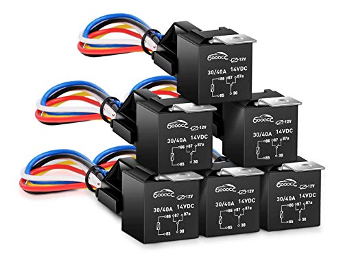
So after a lot of experiments, I was able to make my previews alarm system work with Ring. I used these GOOACC 6 Pack Automotive Relay Harness Set 5-Pin 30/40A 12V SPDT with Interlocking Relay Socket and Harnesses https://www.amazon.com/dp/B01M74X0ZK/ref=cm_sw_r_cp_api_i_rE8ODbQ0F5D45
I was able to attach a sensor to one of these. These trays will act as electromagnets when powered by a 12v battery(which most prewired systems have).
I located the (AUX) on my alarm panel and then connected one end of the wire from the relay to it and the other end to the recessed sensor wire. And then brought the ring contact sensor close to it and it triggered open close on the app. I was able to test it by opening the door.
It worked!! I will post pictures later
https://www.amazon.com/dp/B017743I7S/
This opens/closes a relay that you can wire into a contact sensor of some sort. Plug it into the clapper and you can do whatever automation you want with it. Normally use these on control4 systems, so not sure what zwave/zigbee/usb contact sensors are out there.
If Fibaro's smart implant was available this is the perfect use case.
https://www.fibaro.com/us/products/smart-implant/
Since it's not available you can still use the Fibaro RGBW module over ZWave in Input/Output mode and control the DC circuit of the speaker.
☝️This is how I would implement it.
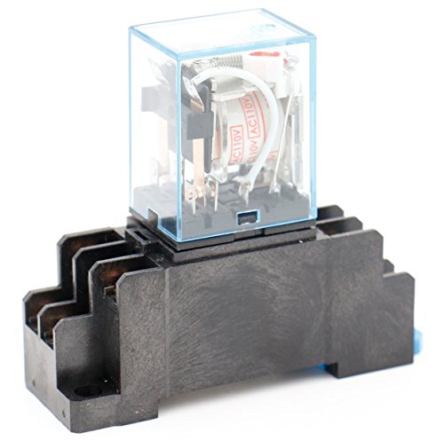
Another solution is use any ZWave/zigbee relay module and use a AC-DC Relay.
(https://www.amazon.com/Uxcell-a14051000ux0379-JQX-13F-Power-Relay/dp/B00NWHJ5N6/ref=pd_aw_sim_263_3?_encoding=UTF8&pd_rd_i=B00NWHJ5N6&pd_rd_r=beb5c684-2d9d-11e9-9da1-2f38c3bf93b4&pd_rd_w=HxKEf&pd_rd_wg=VItgd&pf_rd_p=469620d9-3e90-496d-9dc8-b19f900ba5fe&pf_rd_r=2TB1210HZWRKN4Z6NFBF&psc=1&refRID=2TB1210HZWRKN4Z6NFBF).
Set up something like this so that if the volume goes higher than a certain amount, it cuts the power to the echo for a period of time (that's the reverse of the normal usage).
https://www.amazon.com/Control-Relay-SODIAL-Sensor-Adjustable/dp/B01I2W7VZ4
What makes Nold interesting is the ability to control 2 doors as well as attach a magnetic sensor to let you know the open/close state. This is why I loved the WeMo Maker so much.
If you want an inexpensive garage door opener, use this with a WiFi outlet:
Enclosed AC/DC Power Relay with Protection & De-Bounce. Screw Terminals. 120V Trigge... https://www.amazon.com/dp/B017743I7S/ref=cm_sw_r_sms_c_api_Zi7KBb1KYGJB2
Those wires are going to be battery, flasher out, and ground. For standard filament bulbs, just buy a 2 prong standard mechanical relay and leave the ground disconnected. If you upgrade to LED bulbs, switching to a load independent relay (usually 3 prongs) will fix the fast blink issue.
In the 3 prong the coil side seeks ground for discharge through the additional ground, otherwise it has to discharge through the circuit. Because the load (resistance) is low with LED bulbs, the capacitor that controls the coil latch timing can discharge really fast and the flasher blinks fast or not at all. There are some electronic relays without a standard coil/cap that have a rheostat in them that allows you to adjust the discharge load. Those will be 2 prong - they discharge through the bulbs/circuit. The standard mechanical relays are available at any auto parts store.
Electronic solid state 2 prong with adjustable load:
https://www.amazon.com/AUDEW-Electronic-Signal-Flasher-Motorcycle/dp/B011BTMDQM/ref=sr_1_4?ie=UTF8&qid=1493815500&sr=8-4&keywords=electronic+flasher
Standard mechanical coil 2 prong:
https://www.amazon.com/Bussmann-NO-552-12-8-Thermal-Flasher/dp/B000GKAZCW/ref=sr_1_1?ie=UTF8&qid=1493815609&sr=8-1&keywords=12v+flasher
3 prong with load independent grounded coil (my preferred type - these still need some load to function):
https://www.amazon.com/uxcell-Vehicle-Blinker-Flasher-0-02-20A/dp/B00BLZ9XQK/ref=pd_sbs_263_2?_encoding=UTF8&pd_rd_i=B00BLZ9XQK&pd_rd_r=B9EGDRDCQ81ZH9VWKT7A&pd_rd_w=SRsBN&pd_rd_wg=UBlTA&psc=1&refRID=B9EGDRDCQ81ZH9VWKT7A
Another relay I was looking at was THIS ONE which is about half the price of the one you mentioned; would something like this work fine if I just used one pole? Sorry for all the noob questions...
Edit: THIS is the first relay I considered buying, and they have it in stock in a nearby electronics shop, but I wasn't sure if it's the right type of relay for my purpose, so I held off on buying it today.
Thanks!
Did some quick research and found some relays that appear to be pretty straight forward.
I already bought and have these however: https://www.amazon.com/Pack-EPAuto-Relay-Harness-Bosch/dp/B072QXDZRD/ref=sr_1_4?ie=UTF8&qid=1550813873&sr=8-4&keywords=12v+bosch+style+relay
​
Is it possible to make it work with these? Would it be as simple as having my "orange circuit" on the 30 and 87 pin and push the 12v to the 86 and ground to the 85?
​
If not, would this work?
https://www.amazon.com/Support-Relay-Spst-4pin-Socket/dp/B00RVCFNCK/ref=sr_1_10_sspa?ie=UTF8&qid=1550819958&sr=8-10-spons&keywords=SPST-NC+12v&psc=1
​
edit: I put a 10k resistor on the circuit so I could test the open and close when 12v was introduced. I used the example explained above, under the first produt link, as my circuit. When there is 12v power applied, the circuit is closed and it reads 10k. I need to reverse that, where the circuit is always closed without power and only opened when power is introduced to the relay. Do I have the wrong relay?
​
Thank you so much!