Best pushbutton switches according to redditors
We found 187 Reddit comments discussing the best pushbutton switches. We ranked the 103 resulting products by number of redditors who mentioned them. Here are the top 20.
We found 187 Reddit comments discussing the best pushbutton switches. We ranked the 103 resulting products by number of redditors who mentioned them. Here are the top 20.


I would only suggest doing this mod if you are extremely comfortable with a soldering iron. I'm not responsible if you mess up your Joy-Con. With that being said below are the things I used to make this possible:
Parts
Steps
More pictures
A few weeks ago I posted some pics of a "quick and dirty" induction heater I made:
https://www.reddit.com/r/vaporents/comments/8igobf/gear_shot_yet_another_quick_and_dirty_dynavap/
The heater I built in the previous post worked great, but I wasn't happy that it heated continuously when it was powered on. I decided to add an "on demand" mode, similar to the way the Portside functions: I wanted the induction heater to be energized only when the vapcap was in need of being heated.
I decided to use the same method and hardware that the Portside uses for its triggering mechanism: a small momentary switch at the base of the coil, utilizing the same 12 mm x 12 mm Arduino 'tactile' input switch as the Portside. This switch is normally open but closes (and activates the circuit) when the vapcap is inserted in the induction heater opening and lightly pressed down. I mounted this to a 25 mm square Zip tie "sticky base" using a small dab of hot glue, and ran the wires under the base through a drilled hole. I am happy with how it came out.
I took one other feature from the Portside design and decided to use a MOS FET triggering module to handle the actual power switching, sparing my momentary switch from having to pass enough current to power the heater.
This is the finished desktop unit - pictures, diagrams and some other notes:
https://imgur.com/a/pzRe3SV
PARTS LIST:
12mm x 12mm Arduino Switches:
https://www.amazon.com/gp/product/B01NCQVGLC/ref=oh_aui_detailpage_o03_s00?ie=UTF8&psc=1
My original 'big red switch' was a pull from an Epiphone Valve Junior guitar amplifier, left over from an earlier project. It looks nice, but it's nothing special - any latching (i.e., non-momentary) single pole/single throw (SPST) switch will do. This site has some switches that look pretty good and could work:
https://www.sparkfun.com/categories/145?page=1
Momentary trigger switch base:
https://www.amazon.com/Self-Adhesive-Mounting-Organizer-Management-Fastener/dp/B074279VJG/ref=sr_1_16?ie=UTF8&qid=1527451422&sr=8-16&keywords=zip+tie+sticky+mount
Like the Portside's trigger, I used a 12mm x 12mm Arduino tactile (momentary) switch. Mine is hot-glued to a Zip tie "sticky base", which has the foam removed and is screwed to my board. I kept the stock Arduino switch button and trimmed its edge to fit inside the tube. There is a small segment of 7/16" wooden dowel inside the tube to achieve the correct height.
Pyrex tube:
Iwodevape Replacement Glass Tank for Cloupor Cloutank M3 Vaporizer authentic
https://www.fasttech.com/p/5236304
MOS FET trigger module:
15A 400W MOS FET Trigger Switch Drive Module PWM Regulator Control Panel
https://www.ebay.com/itm/MOS-FET-Trigger-Switch-Drive-Module-PWM-Regulator-Control-Panel-15A-400W-NEW/331961560311?hash=item4d4a736cf7:g:7IsAAOSwEzxYeEwQ or similar. Just search for the above part description, you'll find the right one. It's a popular Arduino circuit.
If you plan on using a momentary switch, this is the way to go. Don't make the momentary switch directly supply the heater current.
Heater:
Yosoo 5V-12V ZVS Low Voltage Induction Heating Power Supply Module With Coil
https://www.amazon.com/gp/product/B01C71XKZ6/ref=oh_aui_detailpage_o07_s00?ie=UTF8&psc=1
Power jack:
If you can solder:
https://www.amazon.com/2-1x5-5mm-Female-Barrel-Socket-Connector/dp/B01M3WBIA3/ref=sr_1_21?s=musical-instruments&ie=UTF8&qid=1527463812&sr=1-21&keywords=5.5+x+2.1+female
If you can't:
https://www.amazon.com/Sumaote-2-1x5-5mm-Connector-Terminal-Adapter/dp/B0761NL8V6/ref=sr_1_18?s=musical-instruments&ie=UTF8&qid=1527463812&sr=1-18&keywords=5.5+x+2.1+female . Although, seriously, this probably isn't a good project for you if you can't solder.
I know many of you have these for yourselves and don't need any help or parts lists, but this may help those who need a little more guidance.
Updated to add: the above links are intended to show the correct parts, but may not be the cheapest or fewest quantities available.
Cheers!
Parts List
Old telephone ringer box
RaspberryPi
Nixie tube vfdclock from ebay
or from these guys
Powered USB hub
Amazon USB speakers
PIR sensor (to turn on nixie tubes at night)
IR receiver/sender
GPIO buttons (they are pretty cheap, next time I'd use these. Thanks /u/John_Barlycorn for the link/idea!
old sony ps2 remote - I chose this remote because they are cheap, built solid and are in brand new shape (no one used them as a remote) and have easy LIRC support
USB mic
Edit:
forgot the pics!
Edit2: Linked everything
$38.37 (considering you have a soldering iron) and don't mind doing some coding, I'd estimate it would take 20 minutes at most if your not putting much detail into it.
Library: https://www.arduino.cc/reference/en/language/functions/usb/keyboard/
Here's a Youtube video as well, https://www.youtube.com/watch?v=SHIcliL4O14
Push button cover guard.
This is what I use. Round Push Button Switch Protector Plastic Cover Guard https://www.amazon.com/dp/B007Q84R0I/ref=cm_sw_r_cp_api_OILRBb7Q519CK
It should be possible to play the whole game using the keyboard. Before you think it sounds foolish, it'd open up a lot, including the ability to playback macros. Think the clone tool on steroids. People could share sections of their prisons and you could import them by running the macro into your own prison. It'd also help people who have problems using the mouse for extended periods of time but have no problems typing.
Also, how cool would it be to have a button you could hit with your hand to lockdown the prison?
With that button you'd have to do some DIY work and put some USB guts inside, but it'd be significantly more durable than this mostly-ready-to-go option.
Edit: There might be a better way of going about it (I haven't much experience), but it seems using this as the guts should make it work (I was adapting from this guide and Peterjaap's comment on on the same page where he substituted the Teensy for the Trinket).
internal shot
Parts list:
Tools:
STL for 3d printing:
All three files
Wiring diagram:
Terrible MS paint Diagram
Full parts list with links to each product:
Camera:
$36 - Raspberry Pi 3
$30 - Raspberry Pi Cam v2
$9 - 8GB SD card (class 4 or higher)
$3 - M3 hex nuts
$8 - M3 screws 16 mm
Iphone Lens x0.67
$20 - Male/Female Header Pins
$12 - Resistors 10k x 2 + 220 O x 2
$7 - Jumper Wires
$7 - LED Buttons x 2
$35 - Adafruit 2.8" PiTFT x 1
$8 - Pogo Pins
$7 - Clear Red 3mm LEDs x 3
$20 - PowerBank
$6 - Resistors - 2x 10k (included in price before) & 2x 100k
$30 - TowerPro MG92B Servo x 1
$8 - Neodynium Magnets 6X2 mm (8 pieces)
$10 - Micro USB Breakout x 2
$7 - Micro USB Cables x 2
Gif Cartridge:
$26 - Raspberry Pi Zero W x 1
$9 - 8GB SD card (class 4 or higher) x 1
Resistors 10k x 1 + 100k x 1 (included in price from camera parts multi pack)
$3 - Momentary Switch x 1
$35 - Adafruit 2.8" PiTFT x 1
$13 - 3.7 v LiPo 400mAH Battery x 1
$20 - Power Boost 1000C x 1
Tools you may need:
Soldering Iron, Desoldering Gun/Solder Sucker, Screwdriver set, Crimping tool, Pliers, Exacto Knives, Sand Paper(400-1200 grit), Tweezers, Acrylic Spray Paints (Black and White) Krylon or Montana Gold
Github Repo for the code: https://github.com/shekit/instagif
Github Repo for the eagle files, STL files: https://github.com/shekit/instagif-hardware
Total Cost: $369
+ iPhone Lens which varies greatly
What the hell dude... Here is the cleaned one with no junk: https://www.amazon.com/dp/B07PPPG7N2/
To add to /u/tyggerjai...
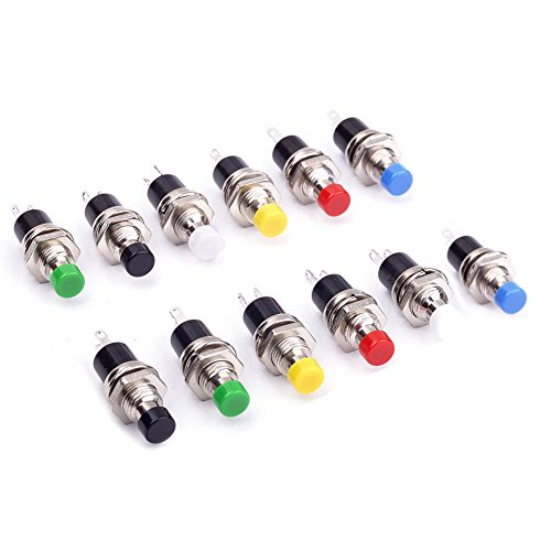
Here is an example of what you might use.
From the picture, this is a 3A rated @300VAC switch. It actually has two sets of contacts, one set Normally Open (NO) and one Normally Closed (NC).
For what you want, you would wire your load onto the Normally Closed (NC) contacts, so that when the switch/button is the in the default position (here, that's "Up" or not pressed) you have a closed circuit to your standard load. You would hook your alarm to the NO contacts, so that it would not be powered.
When the button is pressed, this will kill the power to your main load and provide power to your alarm.
Some points to really take note of:
(I write industrial control software, and since I work for myself I make it a point to NEVER deal with safety in code, so that I am not responsible for it. That's up to my customers to build into hardware; and if I'm not comfortable with their safety systems, I won't work on them.).
EDIT: It's possible that you might want to drive more than the 3A limit of this switch. In that case, I would use a mechanical relay to control your load, and use this button to drive that relay.
EDIT 2: One last thing- always use mechanical relays, and not Solid-State relays for this type of thing. All relays eventually fail, and SSRs tend to fail in the "closed" position, providing power when you might not want it. Mechanical relays are usually designed with a base that you connect leads to, and a plug-in relay module that's easily replaced, like this one.
That's gorgeous. Great work.
My only thought is it's absolutely perfect if you add a safety power switch. A very small detail, but might make a big difference. https://www.amazon.com/Woodstock-D4160-110-Volt-Paddle-Switch/dp/B005W17HYY
This is my parts list.... Simple and it works
The enclosure I used: https://www.amazon.com/dp/B07TS6RY85/ref=cmswrcpapaiAyhxDbV7EHBCN
The 5A power supply (5A and you don't have to use a mosfet): https://www.amazon.com/dp/B01461MOGQ/ref=cmswrcpapaiGzhxDbQWPT5QR
I used a glass slide tube for inside of the coil. You will have to rewrap the coil on the IH to fit around the slide, not hard at all: https://www.amazon.com/dp/B001FWYAWQ/ref=cmswrcpapaiMAhxDbTK5P2YY
The actual IH: https://www.amazon.com/dp/B01GDVVANA/ref=cmswrcpapailChxDb0DGE3TM
The 5v switch w/ wiring harness (you don't need any extra wires this way): https://www.amazon.com/dp/B075QBJVTS/ref=cmswrcpapaifDhxDb7HTYE19
A Unibit would be a good thing to have to get the 3 holes drilled in the box. A hotglue gun and a screwdriver and your set....
Ulincos Latching Pushbutton Switch U19C1 1NO1NC SPDT ON/OFF Black Metal Shell with Blue LED Suitable for 19mm 3/4" Mounting Hole (Blue) https://www.amazon.ca/dp/B017KP67FY?ref=yo_pop_ma_swf
Yeeco Waterproof LED Digital Battery Meter DC 12V 24V 36V 48V 60V 72V 84V 96V Acid Lead/Lithium Polymer/Lithium Iron Phosphate/NiMH Battery Capacity Indicator 6-120V Voltage Volt Meter Multi Tester https://www.amazon.ca/dp/B01MU6V9RD?ref=yo_pop_ma_swf
UTG Tactical Low Profile Rail Mount for Ruger 10/22 Rifle https://www.amazon.ca/dp/B002GNYCJ4?ref=yo_pop_ma_swf
Valken Rifle Accessory Offset Ring Mount, 1" https://www.amazon.ca/dp/B01IU9DV8K?ref=yo_pop_ma_swf
Angled Wedge Hard Rubber Riser Pads with 1.5" Screws (Blue) https://www.amazon.ca/dp/B01LDO3NZU?ref=yo_pop_ma_swf
Bones Bearings Bones Reds Precision Skate Bearings https://www.amazon.ca/dp/B000FDRQ1S/ref=cm_sw_r_cp_apa_gC.RBbKB0KG0H
Homyl Aluminum Alloy Skateboard Longboard Anti Sinking Gasket Prevent Sag Washer - Black, as described https://www.amazon.ca/dp/B07BKS964N/ref=cm_sw_r_cp_apa_SC.RBbNY1EJVH
https://rover.ebay.com/rover/0/0/0?mpre=https%3A%2F%2Fwww.ebay.ca%2Fulk%2Fitm%2F132701686112
Yes they connect to the GPIO. I would use some pushbuttons like this then get some of these dupont cables to connect them to the GPIO on your Pi. Just snip and strip the male end of the cable and solder it to the leads on the button. You'll want to daisy chain one lead from all of the buttons and plug that into a ground pin on the Pi then connect the other lead from the button to an availible GPIO pin shown on this page in the "connecting to the Raspberry Pi" section.
After you have your buttons all connected, you'll need to install Retrogame. It's very simple but Adafruit's guide is pretty bad, if you ask me. I had a hell of a time figuring it out the first time so I'll just explain it to you here to save you time.
Use Putty on your PC to SSH into the Pi (you can find your Pi's IP address in the Retropie menu in Emulationstation, the port is 22, and use the SSH connection type, then the username is Pi, password is raspberry - when you type the password into the terminal nothing will show up, just hit enter when you're done and you'll have direct control over the terminal on your Pi). Now copy this code and right click in the terminal window to paste and hit enter
git clone git://github.com/adafruit/Adafruit-Retrogame
When that's done enter this
sudo nano /etc/rc.local
Enter the following right before where it says "exit 0"
/home/pi/Adafruit-Retrogame/retrogame &
Hit ctrl+x and save the file. Now enter
sudo nano /etc/udev/rules.d/10-retrogame.rules
And enter this in the new document
SUBSYSTEM=="input", ATTRS{name}=="retrogame", ENV{ID_INPUT_KEYBOARD}="1"
Now save the file just as with the previous one.
Now download the retrogame.cfg from the retrogame github and open it with a text editor on your computer (if you don't already have it now would be a good time to get Notepad++) and change the keybinding you want to use for the corresponding pin. Save the file and copy it in the boot directory of your Pi by putting the SD card in your computer.
That should do it.
If you need any help or more information just ask. I know how irritating this stuff can be. I've been wrestling with getting my setup working perfectly for a while and have just recently figured it all out. It's great once it works!
Edit: formatting fixed.
hey man, about to build my first heater tomorrow, I have a list of parts I ordered based on several threads and stuff you and others recommend I came up with this:
https://www.amazon.com/gp/product/B0060U92FS/ref=ppx_od_dt_b_asin_title_s00?ie=UTF8&psc=1
https://www.amazon.com/gp/product/B071NCKQFW/ref=ppx_od_dt_b_asin_title_s00?ie=UTF8&psc=1
https://www.amazon.com/gp/product/B01G00GHQY/ref=ppx_od_dt_b_asin_title_s00?ie=UTF8&psc=1
https://www.amazon.com/gp/product/B00VNSO3OM/ref=ppx_od_dt_b_asin_title_s00?ie=UTF8&psc=1
https://www.amazon.com/gp/product/B003TUMDWG/ref=ppx_od_dt_b_asin_title_s00?ie=UTF8&psc=1
https://www.amazon.com/gp/product/B01GDVVANA/ref=ppx_od_dt_b_asin_title_s00?ie=UTF8&psc=1
aside from wires, a box and tools (Ill get tomorrow from work)
am I set or do I need anything else, also if any of those things I bought incomatible?
Only 10 bucks!
Credit goes to /u/david4500
Pictures:
http://imgur.com/a/eOKIN
Parts:
Get something like this Round Push Button Switch Protector Plastic Cover Guard https://www.amazon.com/dp/B007Q84R0I/ref=cm_sw_r_cp_apa_i_D3IlDbVBHJ2TE
You will need an induction heater
https://www.amazon.com/gp/product/B01ALTHK5W/ref=ppx_yo_dt_b_asin_title_o01_s02?ie=UTF8&psc=1
You will need a power supply
https://www.amazon.com/gp/product/B01461MOGQ/ref=ppx_yo_dt_b_asin_title_o01_s00?ie=UTF8&psc=1
Technically that's really all you need. You could wire the leads to the induction heater and plug it in and it will be on. But I don't think anyone likes the idea of leaving this thing plugged in and always on. Which is why most users will choose some sort of switch set up. For my induction heater I used this one.
https://www.amazon.com/gp/product/B07D373HZF/ref=ppx_yo_dt_b_asin_title_o01_s01?ie=UTF8&psc=1
Several users have pretty in-depth full guides. I think the best and most clear one out right now is this one https://www.reddit.com/r/Dynavap/comments/c94dxj/diy_induction_heater_guide/
Saw a similar issue with mine when I first set it up - switch worked but no lit led.
My issue of course was a wiring problem. For the led to be activated you need to make sure that the additional led connections are made too. This will depend upon the switch you used of course but if you are using something like this https://www.amazon.com/Quentacy-Momentary-Waterproof-Stainless-Suitable/dp/B075QBJVTS?ref_=ast_bbp_dp then check the wiring diagram for program 1. My mistake was I missed that the NO (Normally Open) and the positive LED legs should be shorted to each other. Since mine had a wiring harness I just connected both wires to the positive connection of the zvs unit.
Hope your led issue is a simple fix like mine
BTW I like how you were able to fit it into that compact case, looks cool
I got this switch for my saw. It's the same manufacturer that grizzly puts on their equipment.
http://www.amazon.com/Woodstock-D4160-110-Volt-Paddle-Switch/dp/B005W17HYY/ref=sr_1_3?ie=UTF8&qid=1417293379&sr=8-3&keywords=woodstock+switch
I’ve seen folks use these as well:
Cylewet 12Pcs 1A 250V AC 2 Pins SPST Momentary Mini Push Button Switch Normal Open (Pack of 12) CYT1078 https://www.amazon.com/dp/B0752RMB7Q/ref=cm_sw_r_cp_api_i_57G5CbPJ1XF53
Seems as if you have all the parts you would need for a basic build. I'm still a bit new to this myself, so hopefully someone else will correct me if I'm off the mark.
I used the following parts:
I think that's it. I also have a few additional parts for the lighted push button, but you wont need those if you use a regular one. I can always post that info if you need it.
Check the FAQ for tool recommendations for the basics you would need there.
The SX350 allows for gravity changes (by tilting left/right) to control the wattage and uses it for menu navigation so the buttons are only there if you want more direct control.
edit: If your SX350 does not have the buttons pre-wired there are pads for them on the chip you can wire your own. I believe there is a software update to enable them from Yihi. The one I got from Varitube was already set up for them.
Normal momentary buttons are fine. I used something like This but any tactile switch should work fine.
I have some of these on order as they look/feel a bit nicer then the basic plastic ones i have now.
You might want some magnets for the faceplate. I got some 1/8"x1/8" and 1/4"x1/8" rare earth magnets off amazon and epoxied them in. Check the FAQ for some recommendations on glues and such.
I would also recommend heat shrink tubing and some liquid electrical tape for the solder connections.
Hope that helps.
Well if you must know, Its a cremation box, usually sold for $20-30 on ebay. The Heating module and coil costed 13.00 from https://www.amazon.com/gp/product/B01GDVVANA/ref=ppx_yo_dt_b_asin_title_o05_s01?ie=UTF8&psc=1 The Button costed me 9.99 here https://www.amazon.com/gp/product/B075QBJVTS/ref=ppx_yo_dt_b_asin_title_o05_s01?ie=UTF8&psc=1 and the power supply costed me 11.11 https://www.amazon.com/gp/product/B07NR6FPN9/ref=ppx_yo_dt_b_asin_title_o05_s00?ie=UTF8&psc=1
With shipping and Best offer accepted, i think im doing justice here. These were the best prices i could find at the time from MULTIPLE vendors. I have a Portside Mini in the mailbox tomorrow and THIS box has NEVER failed me in the last few months since built. It is a work in progress yes. It can be expanded and definitely worked on to make it much better. I would of taken $50 which is what they USUALLY sell for but i started it at 75.00. Im sure it will cost me about 7-10 to ship when wrapped properly. Not loony at all.
I'd hate to have a saw start spinning if I leaned over the table and hit the pedal accidentally, or at any point really.
I use a paddle switch like this:
https://www.amazon.com/Woodstock-D4151-220-Volt-Paddle-Switch/dp/B005W17FRS
https://www.amazon.com/Woodstock-D4160-110-Volt-Paddle-Switch/dp/B005W17HYY
With leads or sockets made for removable tools:
https://www.amazon.com/Router-Safety-Paddle-Switch-Removable/dp/B01B1KE4EK/http://www.rockler.com/safety-power-tool-switch
http://www.woodpeck.com/elecswitch.html
https://www.amazon.com/ROUTER-TABLE-PADDLE-PEACHTREE-WOODWORKING/dp/B00153I3IC
Well there is no way to switch 'on' a raspberry pi without additional circuitry
However you could connect to the GPIO pins with something like this. You can connect to the 3.3V pin and connect to a GPIO pin for the switch and monitor it for shutdown event.
Good luck.
Why not just wire up one of these to the button instead?
https://smile.amazon.com/dp/B008ZY9CXE
Found a very similar in Amazon, could be the same you need. The smallest package I've found is for 10 pcs.
6x6x6mm Momentary Push Button Switch 10 pack - 4Pin DIP Micro PCB tactile by Corpco https://www.amazon.com/dp/B01GN79QF8/ref=cm_sw_r_cp_apa_yct3Ab7BS1EDA
Not the person you replied to, but I will try to help.
Electrical switches are relatively simple devices but because there are so many styles of switches available, what you are asking for is really not that simple.
The first question is: What style of switch do you want? Toggle, momentary toggle, push button, momentary push button, rotary, magnetic, rocker? There are literally hundreds of thousands of different switches available.
The next question is how will you be making the connection? Solder, crimp, barrel connector, dupont, molex, scotchlok, screw terminal?
And finally, how and where will you mount the switch? Inline on the wiring harness? Do you need to drill a mounting hole? Are you looking for something that comes with mounting hardware? Is there clearance for your switch location?
I know this is all new to you and I am throwing out a bunch of terms you may have never even heard before. The simple solution for you, at least at first, might be to wire your LED strip right into the output screw terminals of your power supply. Then when the printer is on your light is on, and the light is off when the printer is off. Just be sure to mind the polarity (red to +, black to -) and wire into the 24v dc output side and not the 120v ac input side of the terminal block.
If it helps, here is a short list of switches I have purchased for different projects (all of these require soldering and some kind of mounting hole or hardware):
https://smile.amazon.com/gp/product/B00SUXW18S
https://smile.amazon.com/gp/product/B008DS1GY0
https://smile.amazon.com/ZUPAYIPA-Solder-Rocker-Switch-Toggle/dp/B01N2U8PK0
https://smile.amazon.com/Magic-shell-5-Pack-Rocker-Position/dp/B07D285PLL
https://smile.amazon.com/gp/product/B008ICKO30
I have old (like 50s/60's old) craftsman bandsaw and table saw that someone had rigged light switches on for power at some point, I replaced them with these paddle switches and I love them.
https://www.amazon.com/gp/product/B005W17HYY/
They are kind of bulky so you need a place to put a surface mount electrical box, but other than that they're a pretty simple install using basic crimp-on spade connectors.
Also since you'd put the switch in-line with the cord you could put a longer power cord on it while you're at it, if you're already dealing with a short cord.
When I get home tonight I can snap a couple pics of how I have them installed if it would help.
Didn't take days. Less than an hour, but at the same time I've done about 3-4 of these before so I was already familiar with the inside of a 360 controller.
Here's the tall tactile switches you need for the paddles: http://www.amazon.com/Amico-Momentary-Tactile-Button-Switch/dp/B008420WOA/ref=sr_1_3?ie=UTF8&qid=1394140371&sr=8-3&keywords=tactile+switches
That's 100 of them which is way too many, but only buying 3 or 4 is still only like $1 less...so I bought 100 and they've lasted me through various projects.
You also need (it looks like a lot more than it really is, but I'm being detailed)
You could put a button cover on it, something like this one. You could dress it up and make it look like one of those nuclear launch button covers from movies.
I had one of these, bought for a different project that I switched out, so I had it lying around. It latches open/closed when pushed and a twist of the button unlocks it. So perfect for my project, I figured. The idea is to house the whole project in the base, which is an exercise in layout but a good learning situation.
For safe shut downs, charging warnings, and charging status - Adafruit PowerBoost 1000 Charger - Rechargeable 5V Lipo USB Boost @ 1A - 1000C-Purchased from amazon, https://www.amazon.com/gp/product/B01BMRBTH2/ref=ppx_yo_dt_b_asin_title_o08_s00?ie=UTF8&psc=1
Shell used-Gametown® Full Housing Shell Cover Case Pack with Screwdriver for Nintendo Gameboy Classic/Original GB DMG-01 Repair Part-White (pick whatever color you want)-Purchased from amazon, https://www.amazon.com/gp/product/B01K1C2L1C/ref=ppx_yo_dt_b_asin_title_o06_s00?ie=UTF8&psc=1
Screen used- BW 3.5 Inch TFT LCD Monitor For Car/Automobile – purchased from amazon, https://www.amazon.com/gp/product/B0045IIZKU/ref=ppx_yo_dt_b_asin_title_o09_s00?ie=UTF8&psc=1 (side note here is that in order to make this fit nicer, I installed it upside down in the case.
Speak used - uxcell 16pcs 27mm External Magnetic Speaker Loudspeaker 8 Ohm 0.25W, purchased from amazon, https://www.amazon.com/gp/product/B010V4RAAW/ref=ppx_yo_dt_b_asin_title_o04_s00?ie=UTF8&psc=1 (do not put ANYTHING on the top of the speaker when you install or it will not work.
Prototyping bread board, I purchased from amazon but it is no longer available at the link.
I used this PCB for the buttons on 1 build, the drill guide is VERY useful for this project. - 4 Button PCB For Gameboy DMG-01DIY Pi Zero Made In USA With Grounds and Hole Guide BY:Atomic Market, purchased at amazon, https://www.amazon.com/gp/product/B01JKJCQVM/ref=ppx_yo_dt_b_asin_title_o07_s00?ie=UTF8&psc=1
L-R buttons- 100 Pcs 6 x 6mm x 9.5mm PCB Momentary Tactile Tact Push Button Switch 4 Pin DIP, purchased at amazon https://www.amazon.com/gp/product/B008420WOA/ref=ppx_yo_dt_b_asin_title_o08_s00?ie=UTF8&psc=1
28 Gauge Wire - Ribbon Cable - 10 Wire (15ft), purchased at amazon, https://www.amazon.com/gp/product/B007R9SQQM/ref=ppx_yo_dt_b_asin_title_o09_s00?ie=UTF8&psc=1 (I recommend going to a smaller (higher) gauge than 28. 30 or 32 would have made it a lot easer but 28 will do.
Indicator lights, Uxcell a11092800ux0119 Uxcell (Pack of 75), purchased at amazon, https://www.amazon.com/gp/product/B01F0TCXSW/ref=ppx_yo_dt_b_asin_title_o03_s00?ie=UTF8&psc=1 (these are totally optional)
Resistors and capicitors (audio), purchased from https://www.taydaelectronics.com Note: heres the guide I used for the audio too! https://sudomod.com/forum/viewtopic.php?t=480
Old Gameboy game cartridge. For aesthetics.
Headphone jack, ebay, https://www.ebay.com/itm/3-5mm-Stereo-Female-Socket-Audio-Jack-5Pin-PCB-Panel-Mount-Connector-PJ325-/400959590673
Volume wheel, ebay, https://www.ebay.com/itm/20pcs-B103-16x2mm-10K-Ohm-Double-Dial-Taper-Volume-Wheel-Duplex-PotentiometerBS/293146992835?epid=11009192051&_trkparms=ispr%3D1&hash=item4440ec20c3:g:NZkAAOSw3h1ZUavq&enc=AQAEAAAB0BPxNw%2BVj6nta7CKEs3N0qUCHDbWKwW7sKftQNu9OoIx7SAZoMMNoO7ZC%2BQU2m6tHizIeixg2Hdk8yQin%2B7yNcIdtTzT%2FneqdaLt1WntvDDMDNnZ9%2BCyBsPWRiKLCNPKdeaaZNnBjMoVA%2F0tK%2BtG7DVLtcUKV1a4ZUD8%2F3Lgu9eesPLoBiXZs77Vo7R%2FDaZVMV%2FquPTyLO%2FBFipuEkim1t7BIMiLOi2P3Z31r4yxIdLUw6SCVesvVeqBQuoKov776Dxzk8pUY7PZvu4Q3ULnqBWmlWXsKXc8iAp9juNxUBFHnDgW6A7iElTGYe0sQRXfFHW73jI62f5aO%2FnqGANNK%2F7KJlu474aR3Gae9%2FJCT%2FwoLqmBb4FfizrUJ6qKEuVeLAi31kJSoJXIv4msi3r0bMNSm2D7FL5DUBr0Bc4xsSPi7KFWI9AhmQjUn%2FsLVysgEKd8QEildi1DULaVOX11bv95PGoXvfAusYXSi5NQZk4oZJHr6QIjXu5w4e9Nd2lFtmG4ZB%2BkqROOwwliad72iafj6cbSLphBAjtWGZQVNbmcdKXG6S8h7cTVqt0aD4oej7%2BlDVihmo%2BV0Rc2MhA9FgkM%2BcyzPd0qc9vHvdxjpQUq&checksum=2931469928353c744c25da8843a496116014d4766745
Micro SD card (16 GB minimum)
Female Micro usb Port, (I know I did buy these but I can’t find the link. I bought female micro usb ports to make charging easier.)
I want to say this is the battery that I used, specifically because after taking the shell off it was the perfect fit inside of a gutted Gameboy Game cartridge-https://www.bestbuy.com/site/mycharge-razorplus-4000mah-portable-charger-for-most-usb-enabled-devices-silver/6292246.p?skuId=6292246
3d printed button wells-http://market.sudomod.com/3d-printed-gbz-button-wells/
Extra buttons-https://www.retromodding.com/collections/gameboy
Screw bracket-http://market.sudomod.com/3d-printed-gbz-screw-bracket/
I got A LOT of buttons, glass screen shields, the other three builds button PCBs, some stickers, seriously a lot of stuff from https://store.kitsch-bent.com/ his store is unfortunately closed as he has had life catch up to him and has some shit to attend to. If he comes back online show him some love.
Stuff I got from kitsch
PCB board with LR input points
Buttons for X/Y (you can opt to just get replacement snes or an extra set of Gameboy buttons.
Glass screen that fit the GB shell after removing extra plastic
And obviously you should have a pi zero/w as well a shit ton of patience.
Hi /u/overlyapologeticguy! /u/bntyhntrqueen made me do this.
I just added this to my wishlist. Why, you might ask? Becuase I want to build an electrical light panel and what good would that be without an awesome EMO switch?
(I also added a master switch to the list but I figure I'm supposed to pick one thing to add to your list. So I went with that.)
Hey man. I'm happy to answer any questions you have. I took some more pics but not sure what you're after, so I'll just be detailed .
This Switch is the exact switch I bought
another switch pic
Crappy subs I've had for a decade, the 650w amp just as long, but it still pounds!
Because mobile phone... I posted and kind of explained these backwards I've realized. It's worth mentioning that you start wiring from the front and run it to the back. You need to drop wire from under the hood into behind the glove box. If you started from the trunk you won't be able to push the wire where I did.
You can see where I mounted the line out converter above the sub. And also that the stock Infinity 10 speaker system is still in tact and unaffected by this install. The 8 inch sub is still there.
Front of sub
Here you can see the wiring from front of the car coming into the trunk all hidden. Standard stuff here, around the back seat, under the rear panel, under the scuff panel (where it says Genesis at the door sil), up the panel behind the glove box and into the front of the car (see next picture).
Back of sub
I mounted the fuse holder to the fuse box panel (Genius!) and fed the 4g 12v wire through the grommet in the pic. I had to remove the hard plastic cover and cut a slit in the soft rubber water barrier inside, then drill a hole big enough in the hard plastic outer cover. Feed all of the wire through there and eventually to the trunk. I also drilled a hole near the side of the + batter terminal cover to make a notch for the thick 4g wire to fit.
wiring
Let me know if you wanted to know anything else.
I also posted a while ago about the backup camera installI did which is a nice addition for those who don't have it.
Edit: Added link to other post
I've been told that the 6x6x9.5 or 10mm tacts work best for scuffing. if you want buttons I prefer the 6x6x8.5 tacts with caps.
http://www.amazon.com/gp/product/B00O9VVVPY?psc=1&redirect=true&ref_=oh_aui_detailpage_o01_s00
http://www.amazon.com/gp/product/B00UBWS9IW?psc=1&redirect=true&ref_=oh_aui_detailpage_o01_s00
http://www.amazon.com/gp/product/B008420U92?psc=1&redirect=true&ref_=oh_aui_detailpage_o04_s00
http://www.amazon.com/gp/product/B008MLKJ3C?psc=1&redirect=true&ref_=oh_aui_detailpage_o02_s00
here are some versions I've been playing with. Hope this help!
https://www.amazon.com/API-ELE-Momentary-Waterproof-Stainless-Self-Reset/dp/B079GNNSRP/ref=mp_s_a_1_2?ie=UTF8&qid=1541366661&sr=8-2-spons&pi=AC_SX236_SY340_QL65&keywords=waterproof+push+switch&psc=1
https://www.amazon.com/Quentacy-Momentary-Waterproof-Stainless-Suitable/dp/B075QBJVTS/ref=mp_s_a_1_16?ie=UTF8&qid=1541366661&sr=8-16&pi=AC_SX236_SY340_QL65&keywords=waterproof+push+switch&dpPl=1&dpID=410iuxGxhhL&ref=plSrch
https://www.amazon.com/TOTOT-Automatic-Self-Reset-Waterproof-Dustproof/dp/B07C4T6XT5/ref=mp_s_a_1_19?ie=UTF8&qid=1541366780&sr=8-19&pi=AC_SX236_SY340_QL65&keywords=waterproof+push+switch&dpPl=1&dpID=41UbL7CKvtL&ref=plSrch
There's nothing wrong with your code, I just ran it and it works fine. Are you sure that you are wired up correctly?
momentary switch $8.79 (for 25, you need only 1)
https://www.amazon.com/gp/product/B01NCQVGLC/
induction heater $12.99
https://www.amazon.com/gp/product/B01GDVVANA/
project case: $12.98
https://www.amazon.com/gp/product/B0107WU67M/
mosfet: $7.99
https://www.amazon.com/gp/product/B01J78FX9S/
power plugs $9.99 (you need only 1 pair)
https://www.amazon.com/gp/product/B078YP4CP6/
test tubes $6.02 (cut in half, you'll break a couple until you get one you like)
https://www.amazon.com/gp/product/B00RKMWZOA/
on/off switch $6.50 (for 15, you need only 1)
https://www.amazon.com/gp/product/B01N2U8PK0/
​
in addition, you'll need some 18-20ga wire & solder, and a 12v/6a to 10a power supply
Replying to my own comment with links:
Mosfet:
https://www.aliexpress.com/item/for-3D-Printer-General-Add-on-Heated-Bed-Power-Expansion-Module-High-Power-Module-expansion-board/32706099435.html
Sensor:
https://www.amazon.com/gp/product/B004V6PTKA
Also this e-stop button mounts through one of the holes in the frame. I wired the 120VAC Line through it, better than yanking the plug and also works a little as a child safety.
https://www.amazon.com/gp/product/B00548585A
you could try this for the power.
Awesome man. I cannot tell you how cool I find all this. Science!
Here is what I have purchased so far.
12v 6a 72w power supply
ZVS Heater and Coil Combo
Switch. Can hold up to 20amps not sure that mattters whatever, room for extra isn't bad.
[Glass Tube]I DELETED THIS AS WHAT I HAD HERE IS TOO BIG! DO NOT BUY THE GUITAR SLIDE I HAD LISTED! NEW TUBE. I ordered this from China on a Thursday, let's see how long it takes to get here.
So, I would just be missing the mosfet and momentary switches that you have. Do you find them necessary? I might just buy the mosfet and momentary for peace of mind, but I did see a couple build that avoided the mosfet for simplicity's sake. This build seems to have avoided one.
Any further advice (wire gauge, soldering tips, etc)? I am currently looking for a good box to put it all in. Thanks again for the reply.
EDIT - MOSFET
Momentary Buttons
Mounting things for the momentary buttons
IF ANYONE IS READING THIS IN THE FUTURE, CONSIDER USING A 120W POWER SUPPLY. I DO NOT REALLY UNDERSTAND BUT SUPPOSEDLY IT MATTERS.
I think you need the 12mm ones
http://www.amazon.com/Momentary-Tactile-Button-Switch-12x12x12mm/dp/B008420U92
60V, 110A MOSFET, would this be a viable choice, strapped to something like an old computer heatsink? I'll also need a way to generate a PWM signal to send to the gate.
I'm starting to see the merits of that cheap Chinese controller now. I've never seen a 5 layer pot like that before, I assume it's got an integrated switch?
Once I get the 'throttle' sorted, about the only other thing I'd want to add is an emergency stop to disconnect the battery and short the motor, but that's easy enough to do with one of the DPST NC/NO buttons
I was watching a tutorial on modding a controller and for the back buttons the guy recommended using these
http://www.amazon.com/Momentary-Tact-Tactile-Switch-12mm/dp/B008DGB71Y/ref=sr_1_1?ie=UTF8&qid=1404049555&sr=8-1&keywords=tactile+switch+cap
Hope this helps!
Well isn't the point of doing something or coming up with your own solution - to solve an actual problem? I get the impression that you are looking for a solution to a problem you may never have.
I highly doubt that you would notice a system getting compromised in real time, warranting or justifying the expense of a kill switch. You see that in movies or TV shows but not in real life.
Most intrusions may go on unnoticed for months after the penetration occurred.
I have a Dataprobe iBootBar in my rack, I can run a program on a management network computer or log into its management interface and turn on / off / power cycle 1-8 power sockets for specific pieces of equipment I have.
It's an expensive solution for the typical home user but it works perfectly for it's intended purpose installed in an environment it was designed for.
You could plug the cable / DSL modem into a Clapper - clap on, clap off, the Clapper!
The easiest and basically free solution would be to plug your modem / router / network switch in to a switched wall outlet and flip the switch when you want to kill your Internet connectivity.
That home made thing you found on Amazon looks janky as hell and would most likely introduce line noise / problems into your Internet connection.
So here are three simple solutions, one expensive, one affordable and one free that will accomplish what you want to do.
A real data center / NOC might have an emergency kill switch that could cut power to whatever system they wanted to kill power to, effectively isolating whatever they wanted. If there is one, its there in case of a fire, activating the fire suppression system, not because of network intrusion.
Something similar to this but one made by a better known company would typically be mounted in a hinged clear acrylic / Lexan box to prevent accidentally tripping the switch. It would also be located in an easily accessible location.
Depending on the severity of what that switch affects, the box may even be housed an a 'break glass' box OR be locked with the key taped to the side of the box which would require a positive, two step conscious effort to activate the switch.
Baomain Red Sign Emergency Stop Push Button Weatherproof Pushbutton Switch 660V with Box https://www.amazon.com/dp/B00NTT91Y0/ref=cm_sw_r_cp_apa_qZw3Ab931CZ25.
Too lazy to format links properly. That switch will work. Cut an end off a phone line. Find pins 4 and 5 on the ups. Find what pairs they use on the phone line. And attach them to the. N.O screws on that switch i linked. Then your good to go
Edit. If my googleing is right. It should be the 2. Right most pins closest to the power cable
It kinda depends on what kind of buttons the arcade cabinet uses. The switches can range anywhere from real MX style switches to something like a HAPP Microswitch or even a Sanwa Microswitch.
Either way if its not a cherry mx switch, you'd have to build everything from the ground up such as designing keycaps for the switches and creating a pcb/plate/case for it as well.
I like this idea. Given the small amount of space in most RPi cases, what kind of switch did you use? I see a lot of "panel mount" switches, but the depth of the switch looks like it would be a problem.
Something like this has a much smaller footprint...
https://www.amazon.com/6x6x6mm-Momentary-Push-Button-Switch/dp/B01GN79QF8
...but I am trying to envision how I would mount it on a RPi case.
Thanks! Going with a basic switch with light and using the howchoo guide linked above.
Ulincos Momentary Pushbutton Switch U16B1 1NO Silver Stainless Steel Shell with Blue LED Ring Suitable for 16mm 5/8" Mounting Hole (Blue)
https://www.amazon.com/dp/B01G00GHQY/ref=cm_sw_r_cp_api_Wp7DzbZCH778V
Fingers crossed.
!!!
I don't think Kite specifies a type of button. These will work though: https://www.amazon.com/9-5mm-Momentary-Tactile-Button-Switch/dp/B008420WOA
Don't worry about the dead pixel, that was probably a factory defect. The L button uses a standard tactile switch (if it is similar to the original GBA), you can get a 250 Piece assortment for around $10: https://smile.amazon.com/Hilitchi-200-Pcs-Tactile-Momentary-Assortment/dp/B071KX71SV/ref=sr_1_3?keywords=tactile+switch&qid=1555551801&s=gateway&sr=8-3.
I don't know what the internals of the GBA SP are for sure so I can't really say what the select key is like.
More info @ https://imgur.com/gallery/CG9w4
Everything you need
Sourcing parts is one of the most challenging aspects of these builds. It's a chicken and egg situation in which the parts are defining the design and dimensions and at the same time the design is attempting to define the parts you should look for.
Just as one example, I sifted through tons of portable powerbanks online. The reason I selected the one I used was because:
Similar back and forth's happened for every part that was purchased. I've listed all the parts and split them into those required for the camera and those needed for the cartridge
Raspberry Pi 3 x 1
Raspberry Pi Cam v2 x 1
8GB SD card (class 4 or higher) x 1
M3 hex nuts - McMaster Carr 90695A033
M3 screws 16 mm - Mcmaster Carr 95258A126
Iphone Lens x0 . 67
Male/Female Header Pins
Resistors 10k x 2 + 220 O x 2
Jumper Wires
LED Buttons x 2 https://www.amazon.com/gp/product/B0094GIKDK/ref=oh_aui_detailpage_o00_s01?ie=UTF8&psc=1
Adafruit 2 . 8" PiTFT x 1 https://www.adafruit.com/product/2298
Pogo Pins https://www.amazon.com/gp/product/B008LTKMG4/ref=oh_aui_detailpage_o00_s00?ie=UTF8&psc=1
Clear Red 3mm LEDs x 3 https://www.amazon.com/Transparent-Lighting-Electronics-Components-Emitting/dp/B01AUI4VX8/ref=sr_1_2?ie=UTF8&qid=1503997638&sr=8-2&keywords=3mm+clear+led+red
PowerBank - https://www.amazon.com/gp/product/B01H85P0EK/ref=oh_aui_detailpage_o01_s01?ie=UTF8&psc=1
Resistors - 2 x 10k & 2 x 100k
TowerPro MG92B Servo x 1 http://www.ebay.com/itm/like/182310479953?chn=ps&dispItem=1
Neodynium Magnets 6X2 mm (8 pieces) https://www.apexmagnets.com/6mm-x-2mm-disc-neodymium-rare-earth-magnet
If you aren't making your own USB cables:
Micro USB Breakout x 2 https://www.amazon.com/gp/product/B00KLDPZVU/ref=oh_aui_detailpage_o01_s00?ie=UTF8&psc=1
Micro USB Cables x 2 https://www.amazon.com/gp/product/B00S8GU03A/ref=oh_aui_detailpage_o01_s01?ie=UTF8&psc=1
Raspberry Pi Zero W x 1
8GB SD card (class 4 or higher) x 1
Resistors 10k x 1 + 100k x 1
Momentary Switch x 1 https://www.adafruit.com/product/367
Adafruit 2 . 8" PiTFT x 1 https://www.adafruit.com/product/2298
3 . 7 v LiPo 400mAH Battery x 1 https://www.amazon.com/gp/product/B016ZU9C2K/ref=oh_aui_detailpage_o00_s00?ie=UTF8&psc=1Adafruit
Power Boost 1000C x 1 https://www.adafruit.com/product/2465
Tools you may need:
Soldering Iron
Desoldering Gun/Solder Sucker
Screwdriver set
Crimping tool
Pliers
Exacto Knives
Sand Paper(400-1200 grit)
Tweezers
Acrylic Spray Paints (Black and White) Krylon or Montana Gold
Github Repo for the code: https://github.com/shekit/instagif
Github Repo for the eagle files, STL files: https://github.com/shekit/instagif-hardware
If you can solder make a scuf tbh
I am an electronics refurbisher and I have had scuf like products come in before and a lot of the time they end up being a controller with some holes drilled in it with paddles and a board you can find online for like 15$ and do yourself
https://www.amazon.com/Playstation-Dualshock-Board-Remap-Install-4/dp/B00SVHWMEQ
https://www.amazon.com/gp/aw/d/B008420WOA/ref=pd_aw_sim_63_1?ie=UTF8&psc=1&refRID=JAERDCKTZASCC1X42QMP
my idea would be to just drill some holes into the existing plastic-covers and install something like this or this
chances of getting a oem Kia switch/button will be hard, since the switches will be sold as spare parts, thus already labeled.
I haven't done this myself but I read on here that you can keep the original button and joystick if you buy a push button microswitch like this, https://www.amazon.com/Microswitch-Arcade-Button-Standard-Jamma/dp/B01IJ8VYK4/ref=mp_s_a_1_11?ie=UTF8&qid=1541467443&sr=8-11&pi=AC_SX236_SY340_FMwebp_QL65&keywords=arcade+button+micro+switch&dpPl=1&dpID=41ZSINy0f9L&ref=plSrch
I'm not sure if that is the right one, but it is something like that to get the button to register, the stock button are all glued up and too much work to clean. You'll also need wire, USB encoder, usb wires. Not sure about the joystick though. The goal is to convert the joystick to USB so it can register in retropie/ raspberry pi.
When you add it all up for what you need to buy and do, it makes much more sense to replace everything like what most people are doing here. I bought a 2 player joystick set with lighted buttons on Ebay for $36. Not the best set but it is a little better than stock and a lot easier to work with.
Just make sure to look for buttons that are size 30mm since the hole on the unit are for size 30 mm. My set came with 16 30mm buttons and 4 24mm buttons.
Any bike can be keyless and have cruise control. You just need these Two Things.
https://www.amazon.com/Electrical-Buddy-Rainproof-Pushbutton-Switches/dp/B07PPPG7N2/ref=mp_s_a_1_1_sspa?keywords=electrical+push+button&qid=1574794584&sr=8-1-spons&psc=1&spLa=ZW5jcnlwdGVkUXVhbGlmaWVyPUEyS04wQzhOUjBMQldRJmVuY3J5cHRlZElkPUEwNTU2MTY5MjdOQzRROURKTVZXSiZlbmNyeXB0ZWRBZElkPUEwMDQyNTgxM1VVOUIzUzRBR0JBOCZ3aWRnZXROYW1lPXNwX3Bob25lX3NlYXJjaF9hdGYmYWN0aW9uPWNsaWNrUmVkaXJlY3QmZG9Ob3RMb2dDbGljaz10cnVl#immersive-view_1574794607102
Edit: posted actual link, as the shortened one was understandably suspicious