Best interconnect terminals according to redditors
We found 323 Reddit comments discussing the best interconnect terminals. We ranked the 201 resulting products by number of redditors who mentioned them. Here are the top 20.
We found 323 Reddit comments discussing the best interconnect terminals. We ranked the 201 resulting products by number of redditors who mentioned them. Here are the top 20.


Having a set of these https://www.amazon.com/dp/B075TYSD26/ wire crimp connectors with shrink wrap is a great idea.
If this were me, I would likely use some Scotchlok Butt Connectors. They would provide a more secure connection, and are very common in telecom/data cabling. Link To Scotchloks on Amazon.
Edit: The best part, the only tool you need is a pair of pliers. No guarantee this will fix the problem, but it should help- either way it’s a better way to connect them, compared to twisting the wires.
They do make small female spade connectors that will fit on the end of them. But the spade on the end of those switches isn't technically long enough... but it'll work.
Oh... You just wait till they whip out the butt connectors!
https://www.amazon.com/Shrink-Solder-Sleeve-Crimpless-Connectors/dp/B01M1032A7?th=1&psc=1
https://www.amazon.com/Connectors-Waterproof-Electrical-Terminals-Automotive/dp/B075TYSD26/ref=mp_s_a_1_3?ie=UTF8&qid=1542647519&sr=8-3&pi=AC_SX236_SY340_FMwebp_QL65&keywords=splices&dpPl=1&dpID=512rF%2BLN5JL&ref=plSrch
Or use butt connectors with heat shrink, to keep any moisture out of the connection:
https://www.amazon.com/Forney-54827-Connector-Shrink-25-Pack/dp/B009PHFNN8
here you go, the modern gold standard. Solder Seal heat shrink tubing.
Jesus, have you never heard of insulated butt splices? Solder-and-seal connectors are even better.
You should be using quick-connect crimped terminals. That's why they have the blades like they do.
Soldering can actually damage the internals of switches from overheating.
Don't get the kind you linked to with the metals exposed. Get fully insulated ones like https://www.mcmaster.com/#7243k111 https://www.amazon.com/dp/B010GWZOUW/ref=asc_df_B010GWZOUW5487366
If you really really really hate the idea of soldering, you can use these: https://www.amazon.com/Shrink-Solder-Sleeve-Crimpless-Connectors/dp/B01M1032A7
They solder and heatshrink and encapsulate all at once, which is amazing, but they're expensive.
Edit: Also, if you want an iron that's amazing for working on cars, here's the unit I use. It's a butane powered iron. Gets hot in like 10 seconds and works way better than the $25 firestarter turds they sell at the hardware store. http://www.all-spec.com/Catalog/Soldering-Rework/Soldering-Irons-Accessories/Soldering-Irons/UT-100SI-32612
I wonder how many people commenting here actually have a Trailtech product? I have two of them.
You can wire it directly to the battery if you would like. It won't run the battery down. They shut themselves off automatically. They also have their own, internal battery to run the clock. I have my CRF250X set up this way. It has a very... minimal electrical system, there almost isn't any outlet for switched power.
You could also run it off of the tail light or license plate light if you want switched power. Posi-Tap connectors would make this very easy.
Something like this. https://www.amazon.com/Posi-tap-Connector-20-22-Gauge-Wire/dp/B00389UT3I
What's the problem with splicing? It's not permanent. You just remove it when you don't want it anymore. Get these.
As far as finding switched power, get a wire tester and poke some wires with it while turning the key on and off. When you find a wire that's hot when the key is on and dead when they key is off, use that wire.
Or you could just buy some new spade connectors
Edit: one of these sizes should work.
No, you still wouldn't ever want to do it that way. Just use a standby UPS plugged into the same circuit as the primary supply. Least sketchy way to do it would be to score the power cable along the length for a couple inches and around the circumference all the way through and peel off the jacket to expose the three inner conductors and slap on a t tap on each one. Then just wire up an adapter going from a standard NEMA 5 plug to the spade terminals from the t taps.
https://www.amazon.com/Ginsco-Terminals-Self-stripping-Insulated-Disconnects/dp/B01CDWC60Y
All you would do to switch it over is plug the cable into the UPS first, then plug the spade connectors into the t taps, unplug the original power cable from the wall and immediately plug it into the UPS, then unplug the spade connectors and remove the adapter cable.
I like how you think. True, the NEC would say "with listed parts per manufacturer specification" unless there is something I haven't seen, what others are mentioning here is for small wire that cuts into the sheathing and makes contact with the wire for teenagers shitty car audio systems.
I would think using a decent sized screw and lugs you could realistically get 70 amps worth of contact area. Have to do some testing to make sure it's not breaking strands, but going between them
Get some spade terminals to crimp on the wire. I've had a lot of issues with the thread the wire through and twist it approach. It works fine at first but often tends to work loose and oxidize over time and starts cutting out.
> I would be indebted to you if you reminded us what you did and how you did it. I love creating DIY gizmos, and recall your setup being a very manageable blueprint.
I suppose we can arrange that.
---
TL;DR - 101 Ah Battery, DIY Distrubution Box w/ Banana Plugs, Mount/CCD/Arduino power cord converted to banana plug, 12V Laptop Power supply and 110V DSLR power supply hacked up, a few bits and pieces, couple of solar panels thrown in for fun.
---
The long version
===
What's important is that this be a DeepCycle or Marine battery, designed to deliver low current for extended periods of time (vs LOTS of current QUICKLY, like when starting a car) and be drained to low amounts of remaining capacity and recharged many times.
You completely do not care about "CCA" - Cold Cranking Amps. If your rig ever draws more than 10-ish Amps or so at one time, you have much bigger problems than whether your battery can deliver it. :)
What you're after is capacity, in AmpHours. I'll talk below about how to calculate your needs, if you're really wanting to be picky...but suffice to say, 50-100 Ah should be plenty for any normal AP use, especially if you'll be charging after every evening.
Mine has banana plugs on the input side, so I can plug it into my 12V power supply when I'm at home. When i'm in the field, I have some battery clips that you can plug banana plugs into like these, but you can also rig up your own if you wish with some simple 3/16" brass tubing and some solder. :)
BE VERY CAREFUL HERE The company that makes these uses black for negative, and red for positive. Great way to get confused and short your power supply, etc.
Next, read the power supply to see what its output is (or use a multimeter to find out). It is a pretty safe bet it'll be 7.4V, since that's the output of a 2-cell lithium pack, which is what most of them are these days, but check and be sure.
The, grab yourself a little step down module (You can find those in packs of 10 or more for less per piece if you think you need extras for other projects), These guys are slick....just hook up your power supply and a voltmeter, twist the little gold screw to adjust output power, and when it gets to 7.4V (or whatever your DSLR needs) you're all set.
Clip off the output cable and plug from the DSLR power adapter, solder that onto the output side of the step down module, hook up some banana plugs to the input side...done. 12V DSLR power for the night.
next to the RV. No picture, I'm too lazy to drag them out of the RV storage. heh I do want to be clear, though...having some solar recharging capacity is not necessary at all unless you're just crushing this rig for power (see below), but it IS pretty cool and gadgety if you're into such things. :)
---
Easy...you need the number of amps your rig pulls, times the number of hours you'll be using it, times the number of times you want to use it between charges, times 1.5
The two biggest consumers in a typical AP rig will be the laptop and the cooler on a CCD if you have one. DSLRs, focusers, tracking mounts, etc...None of these things use much power at all, and they use VERY little on a constant basis.
Best way to know for sure is simply to use a multimeter to measure the current each one is using under its highest load. In other words, measure the mount while it's slewing, the CCD while it's cooling, the laptop while it's screen is on and drives aren't sleeping and battery is charging, etc.
Add all those up, that's your current needs....you need to be able to provide that many amps at any given time. (That number almost CERTAINLY ought to be under 10A, hence the suggestion of a 10A fuse above).
Now...multiply that number by the number of hours you'll be running the rig. Say you pull 5A, and will be imaging for 6 hours. That's 30AH of capacity you'll use (if everything's running at max).
Now..maybe you want to be able to go camping for a weekend, and not recharge...so you want to shoot for 2 nights. Ok. 30Ah 2 = 60Ah.
And finally, give yourself a nice cushion, so you don't drain the battery completely (a deep cycle CAN handle it..but they still don't "like" it). Let's say 1.5 times the need, so 60 1.5, 90Ah.
You can quite comfortably figure on a 90Ah battery getting you two full nights of use, with no worries. :)
For what it's worth :
I run a cooled CCD, a Losmandy G11 mount, a Toshiba laptop, an Arduino-based focuser, AND support my son and I recharging our RC batteries (various 1.8Ah - 4 Ah capacity 2-6 cell packs) all off the same 101Ah battery. We can pull a complete weekend (leave on Friday afternoon, image Fri/Sat nights, fly Sat/Sun day) RC/Imaging camping trip and come home with about 20-30% capacity left in the battery. With the solar rig added on, we could go 4-5 days or more, depending on sunlight. I did my recent 3 night imaging trip with the same battery, and wasn't even down to half-empty when i got home.
Ah, so the issue is that you only have one battery on the board at one time, and the charging port is on the board. So you can't charge one while you're riding?
The best solution (in my opinion) is to get a new enclosure that can hold both batteries, and then wire them up in parallel with an xt60 y-connector and the jst y-connector linked above. Swapping batteries on the meepo involves too many screws and too much fuss to sound super practical for me. Apparently this enclosure can hold two (or even three) of those batteries comfortably- https://psychotiller.com/product/the-durban
With that said, soldering those parts above would definitely work. I'd use solder seals personally, they're the easiest way to permanently bond (and insulate) wires together
https://www.amazon.com/HOODDEAL-Waterproof-Solder-Connectors-Soldering/dp/B00ESXX74G
It's a low-temp solder+ thick shrinkwrap + adhesive all in one. Good stuff for pretty much any electronics use (if you didn't know of them already).
Putting both batteries on one charger would definitely increase the charging time. Course, you'll also need to charge it less, because bigger batteries. So, there's that.
Check out this thread for more info- https://www.reddit.com/r/ElectricSkateboarding/comments/75zkqv/meepo_battery_upgrade/
u/Jreamer said he used the connector I linked above, seems to have no issues with it (that I've heard of).
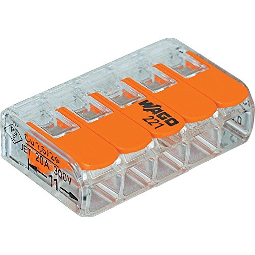
I second Wago connectors, These are what i would use.
https://www.amazon.com/dp/B06XH47DC2/ref=sxbs_sxwds-stvpv2_3?pf_rd_m=ATVPDKIKX0DER&pf_rd_p=6375e697-f226-4dbd-a63a-5ec697811ee1&pd_rd_wg=hr3Yf&pf_rd_r=ZYXJFJQHX01M7APC8JBR&pf_rd_s=desktop-sx-bottom-slot&pf_rd_t=301&pd_rd_i=B06XH47DC2&pd_rd_w=TPn4N&pf_rd_i=wago+connector&pd_rd_r=6ee3ce01-8e70-4bdb-9718-965ceb4fcdc1&ie=UTF8&qid=1541084967&sr=3
Check this out at Amazon.com
Wago 221-413 LEVER-NUTS 3... https://www.amazon.com/dp/B06XGYXVXR?ref=ppx_pop_mob_ap_share
I got red and black...
Check this out at Amazon.com
Remington Industries... https://www.amazon.com/dp/B010T5Y6PU?ref=ppx_pop_mob_ap_share
Check this out at Amazon.com
Cable Matters 2-Pack 16 AWG Heavy... https://www.amazon.com/dp/B00WA0W62S?ref=ppx_pop_mob_ap_share
Check this out at Amazon.com
ATPWONZ IP68 Waterproof... https://www.amazon.com/dp/B01NALYPFT?ref=ppx_pop_mob_ap_share
You want the one labeled car radio accessory switched on the list on this page.
http://www.modifiedlife.com/2003-jeep-grand-cherokee-car-stereo-wiring-diagram/
You want to use something like this to add the wire for the power to the module.
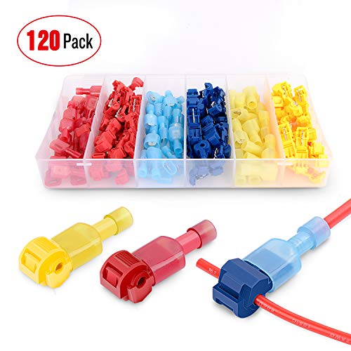
Ginsco 67pcs 24-10 AWG Quick Splice Solderless Wire and T-Tap Electrical Connector Assortment Kit with Case https://www.amazon.com/dp/B01L74LNCG/ref=cm_sw_r_cp_apa_N48aAbKZWEH7C
It squeezes over the wires and punctures the insulation. Very handy to have around for all sorts of stuff.
I would mount something like this in the dash somewhere and connect the headphone jack from the module to the back. Use another cable to connect to your phone. This way the replaceable cable from the dash to your phone takes the abuse and can be replaced when it breaks instead of having to replace the module and tear apart the dash again.
Philmore 3.5mm 4-Conductor Panel Mount Stereo Jack with Nickel Plated Metal Housing : 45-396 https://www.amazon.com/dp/B073MSCPPR/ref=cm_sw_r_cp_apa_178aAbDEFDM4N
It would have been easier and probably better sound quality to just get an aftermarket radio.
This picture shows a pigtail connection.
Basically, you will join all the black wires, and all the white wires together using a cap or better yet, a set of these. in those groups you will also add a new ~5" section of wire to connect the outlet.
I wouldn't suggest trying to get all 3 sets of the current wires to the outlet, because if you dont get it tight enough you have a point of failure. ARC = Fires
Hm, it's not very complicated though. If you cut the cable, there are 8 wires inside: 3 black ones, 3 yellow ones, a blue one and a red one.
You connect all the black ones and the blue one together and wire those to the negative wire of a socket like this. Then you take the three yellow ones, connect them together and wire them to the positive wire. Done.
If you're not sure how to connect the wires together, these are more or less perfect for the job. Maybe you can find them locally.
wire nuts? Those dont get used on automotive connections EVER. These crimp connectors do https://www.amazon.com/Wire-Crimp-Connectors-Blue-Yellow/dp/B002T1FLPM and you crimp them onto the wires and then wrap in electrical tape.
Sure. You can do it a couple ways -
I HIGHLY recommend cutting off the cheap female spades that are on the Katana's speaker leads and replacing them with some crimp on INSULATED female spades like these:
https://www.amazon.com/Yueton-100pcs-Insulated-Terminal-Connectors/dp/B010GWZOUW/ref=pd_lpo_vtph_60_bs_t_1?_encoding=UTF8&psc=1&refRID=3X943RD62DVH2NFTZ8RZ
You can find them at any hardware store, and will protect the spades from touching each other if you accidentally turn the Katana on without having the leads connected to a speaker and prevent them from shorting between each other and damaging your Katana.
Here is a small diagram i threw together for soldering in an additional fan into power pads beneath the board. I have switches in here because i plan on having a switch for the part cooling fan so i can turn it off when i want to print ABS parts.
Also, get these connectors so that you only have to solder one + wire and one - wire to the mainboard, strip 11mm of wire and plug the + into one connector and the - into another connector. Now you have the ability to add 4 accessories like extra fans or LED lighting.
Something like this: https://www.amazon.com/Auto-Truck-Relay-Socket-SPDT/dp/B007JPPQH6
They sell them at every auto parts store in the country. A few different variants on wiring. Look up how to wire a relay, not too hard. You will need to get an ignition-tied 12 volt signal from somewhere, yes you'll have to tap into the factory wiring but there are a million places to do this behind the dash/fairing/gauges/ignition.
There are several products that you can use that will not require using wire nuts, which can be large and difficult to work with in confined spaces with not enough wire. This is one of those products, meant to lengthen wire-connections for various reasons. You will along with this product, need another 2-3 inches of copper wire, the same kind that is the wire of the door bell. You crimp, or squeeze this product on to the end of the wire, without the copper protruding from the wire, and use another piece of wire to extend the connection to your doorbell. With this product you will cut off the visible copper from the wire, and attach the product on the wire including its colored insulation. You might benefit from going to a store that has electrical stuff, and having someone guide you through what you'll need. Needle nose pliers, wire cutters, etc. Hopefully my description is sufficient. Good luck.
Sure thing:
Charger Port
https://powerwerx.com/panel-mount-dual-usb-device-charger?gclid=CjwKEAiAvZTCBRDvnoOaoa2j3xISJABxPjN9lAYkK9VHJy09GpoVvsMyWgTRaMPgoooQ8iCKM6-xxBoC3IDw_wcB
Relay
https://www.amazon.com/Auto-Truck-Relay-Socket-SPDT/dp/B007JPPQH6
The pid:
https://www.amazon.com/Digital-REX-C100-Temperature-Controller-Thermocouple/dp/B07QS2W736?th=1&psc=1
It’s Celsius but it’s only $19
These heaters $10
https://www.amazon.com/YXQ-Cartridge-Electric-Heating-Fittings/dp/B06XWB86GF
These connectors are good 10 pack $8.45
https://www.amazon.com/Wago-221-413-LEVER-NUTS-Conductor-Connectors/dp/B06XGYXVXR/ref=mp_s_a_1_3?keywords=wago+connector+3+ten+pack&qid=1570302206&sr=8-3
These cable glands. $2.54
https://www.amazon.com/uxcell-Plastic-Waterproof-Cable-Connector/dp/B00EZ76W74/ref=mp_s_a_1_2?keywords=pg11+cable+gland+2+pack&qid=1570302379&sr=8-2
Power cable and switch if you want one just take out the switch and rewire it in your box. (Soldering required for switch) $5.49
https://www.harborfreight.com/6-outlet-power-strip-64144.html
You will need 1 foot lengths of the following 16 gage braided wire
6-black
5-white
2-green
Put it all in a DIY box (budget)or you can get one of these: $9.61
https://www.amazon.com/BUD-Industries-CU-3283-Plastic-Utility/dp/B005T5A0W4/ref=mp_s_a_1_1?keywords=hobby+box+bud+industries&qid=1570303560&sr=8-1
These work well but I’m starting to like my wood box made from old growth plywood salvaged from an old house. Plus it takes the build cost down $9 if you build your own.
Total cost $46
$55 if you buy the box
I don't remember what they were called, but I've used some heat shrink butt connectors in the past. They had a melting sealant inside them that oozed out of the ends when they were shrunk. Some have been in very wet ground since 2010 without any issues. Also on 24V.
These might be the same connectors.
So... I have to ask... did you know a resistor and a relay are completely unrelated functionally? As in, resistor resists, adding a load to the circuit, (for various reasons needed) and a relay uses a signal from one circuit to complete a wholly separate, circuit.
Therefore, I don't know why you'd use a resistor in place of a relay. Like, at all. Perhaps I need enlightenment there... :)
As far as what relay, in a car, a standard 12v car 'box' relay will do. This one's cool, it comes with a socket it plugs in to. These are cheap and just lying around in any auto parts store, however, and you can use female spade terminals if you want and just bolt it in somewhere handy.
Don't forget either an inline blade fuse holder or an AGC one, and I'd fuse it for, oh, 5 amps. Shouldn't need much, just make it fast blow, and enough amps to ensure the lights won't blow it, but it'll blow in a short. LEDs shouldn't need a big fuse, really.
Hope that helps ya.
Buy one of these:
http://www.amazon.com/1-X-9V-Battery-Connector/dp/B001F39728
Cut the wires.
Read this: http://www.instructables.com/id/How-to-strip-and-connect-wires-with-a-butt-connect/
Attach new connector with these:
http://www.amazon.com/Forney-54827-Connector-Shrink-25-Pack/dp/B009PHFNN8
Is It ?
​
Now I won't say replacing your radio is a walk in the park. But its pretty straight forward.
Thats mainly it. Of course google search your make and model for any detailed youtube video and look up some popular channels to see what help you can get. You'll appreciate your old speakers again. I have a $20 dual head unit i bought, but you can get other quality head units for $50. If you become confident from installing a cheap head unit. You can sell that shit and get a new shiny android auto or apple carplay headunit once you leave povertyfinance !
Ditch the converter for a NOCO battery charger/maintainer. You will thank yourself later. This one does fine with a 55Ah AGM battery. Also, don't use a wet cell battery unless it's in its own box outside the trailer.
I like your fuse block. I fused the battery feed to mine at 30A, and sized the wire accordingly - 10AWG boat cable would be perfect. All the fuses in my Blue Sea Systems fuse block are 10A and under.
Grab some LED voltmeters and mount one inside and one near your fuses. And one in your car, and....
Unless you need a separate distro bus, I'd skip that. I am using Wago 221-415 connectors as mini bus bars as needed - run a wire from the fuse panel into the cabin, then up to four additional circuits from that point - lights, etc.
You will find that your main switch panel is less functional than you hoped it would be. I recently removed mine. Individual switches at point of contact are much more user-friendly.
We loved our Fantastic Fan, and I've heard great things about Maxx Fans, but we went back to a solid roof with vent fans in the galley bulkhead.
Multicolored LED strips are fun! We are currently installing two circuits of them in the galley. When you set yours up, make sure you install a controller with non-remote controls. We have had some of the remotes fail, and at least one of them couldn't be replaced. Superbright LEDs currently has a stunning deal on one that fit our needs.
LED strip channels are a good idea. Also get the long clips, which hang on to the channel better.
Your under-cabinet lighting is probably on a 12V wall-wart. Cut it off and hook the LED strips right into your 12V system.
For wiring, get a spool each of 22AWG, 18AWG and 14AWG tinned copper cable; molded cable (lamp cord style) is acceptable. We have used Wiremold NMW1 raceway and surface mount boxes to keep things simple and tidy. Where things turn corners we leave the wires exposed instead of going nuts with the corner and tee fittings.
I have a hard time believing that crimps are preferred to properly soldered wire + heat shrink. For one you can still have water/corrosion issues with crimps and another crimps are just not as mechanically sound as solder+heatshrink. Unless you are talking about some other type of crimp besides these:
http://www.amazonsupply.com/wire-crimp-connectors-blue-yellow/dp/B002T1FLPM
So you'd have to solder on a new connector. You can use a 5 pin harness, just splice both ends and combine with your current one that just has the bare wires exposed. Another option, if your encoder has the 2 pin connectors for UP, DN, RT, LT, then you could take four 2pin connector cables and solder those onto the exposed wire. 4 of the 2pin connectors need to connect to the black exposed wire (ground) and then the remaining 4 match up with the other 4 depending on color and direction which you can find out here.
If you can't solder, you can use Lever Nuts(they have 2, 3 and 5 sized connectors) or connectors like these or terminal blocks like these.
EDIT: Sorry for not giving credit where credit is due. This was mostly taken from this post here. It has a lot of pictures to refer to as well. Good luck!
You can solder or there are a variety of solderless connectors out there. A lot of people take the opportunity while they're replacing the fan to add in some type of connector (JST is popular and fine for something low current like a fan) to make any future swaps easier. If you're a bit timid about soldering you can use something like this - solder shrink connectors. I've never used them but have seen folks on another printing group recommend them. They're pretty much just shrink wrap with a bead of solder in the middle, you just stick the two wires in and heat. It solders and shrink wraps them all in one easy step.
Here you go: https://youtu.be/RWo3EtRsleI
The wire I used was 22 AWG. You'll need some spade connectors and a Molex kit. I used my wire strippers to crimp the spade connectors and Molex pins (I bought a crimper tool, but it unfortunately didn't work for these).
Facts as I understand them (which may not match reality):
If all of the above are true:
And finally to answer your question:
Only do the wire swap once. If you have a ohmmeter, you can check this by confirming that the outside of one end is electrically connected to the inside of the other. You should also confirm that the outside and inside are not connected to each other, or else you're going to have a bad time.
P.S. Barrel connector is also known as a coaxial power connector.
i love these connectors with solder built into them. stick your two wires in and use a heat gun and you're done.
https://www.amazon.com/HOODDEAL-Waterproof-Solder-Connectors-Soldering/dp/B00ESXX74G
You could use something like this - https://www.amazon.com/Shrink-Solder-Sleeve-Crimpless-Connectors/dp/B00IEFOCXO?th=1&psc=1
Stick the wires in. Heat it with a heat gun. All done - soldered, shrink-wrapped and sealed.
No, it doesn't matter at all, you just need a 12 volt power source like the cigarette lighter receptacle. There are also a lot of car modification shops if you want someone to do the installation for you.
If you want to just get one of the inexpensive backup cameras from Amazon you should check out some video tutorials to get started. Some people power the camera off of the reverse light (you know, the white lights on the back of cars when they go in reverse). That means that the camera stays off until you go into reverse. Personally I just leave my camera on, so I power everything off of my Cigarette Lighter Receptacle. Here are the parts I used:
A camera and monitor.
A cigarette lighter receptacle adapter.
A terminal strip. (This connects the cigarette receptacle to the camera and monitor).
Extension cable to connect your camera to your terminal strip.
Wire crimp connectors to connect the camera to your extension cable.
Optionally, but recommended: A cigarette receptacle splitter so you have extra power ports.
Sorry if my way of doing it is a little hacky, but it works. Let me know if you have any questions.
Heat Shrink Solder Sleeve Crimpless Butt Connectors - 22-20 AWG (Red) - 10 Pack https://www.amazon.com/dp/B00IEFOCXO/ref=cm_sw_r_cp_apa_i_M.h9AbMYGR3ZK. Try these I am an aircraft mechanic. We use these on airplanes. All you need is a heat gun and the solder melts and the heatshrink thightens up. Then your done. They are much smaller than other splices people have shown on here.
Its very easy to wire these up. The first image at this link shows a good way to wire them. To do it that way, you need 10 Wago 221-415 lever nuts.
You can use thermal tape to attach the strips to your aluminum frame, if you don't want to drill a bunch of holes. That makes it a little easier to assemble.
Definitely do it yourself. If you have any questions, post them on here, or in the forums on LEDBuilder.com, and someone will help you get it wired up.
When I said "not much room for error", I meant that if one or two strips get disconnected, the driver will deliver more power to the remaining strips than their max rating. That is very unlikely to happen. So, don't worry about it much. Just make sure all your connections are good before you power it up.
Tool wise, you'll need the BBS Luna wrench, allen keys, lots of zip ties, and something to do the wiring.
Two choices for the wiring: Crimping or Soldering.
For crimping, you'll need heat shrink insulated crimping connectors (I got these: https://www.amazon.com/gp/product/B075TYSD26/ref=oh_aui_detailpage_o02_s00?ie=UTF8&psc=1) and a crimping tool that works with insulated crimps.
FOr soldering, you'll need heatshrink tubing, a soldering iron, lead solder (don't get that unleaded stuff).
For both a heatgun would be good to have.
Of course you'll need a wire cutter and wire stripper as well.
Depending on chainring, you'll likely need a new (longer) chain than is on the bike, as well as a chain tool to remove the old one.
You'll also want a Thudbuster or Suntour NCX seatpost suspension and a more comfy seat I think.
Sure do.
Terminal Blocks
4 Conductor Wire
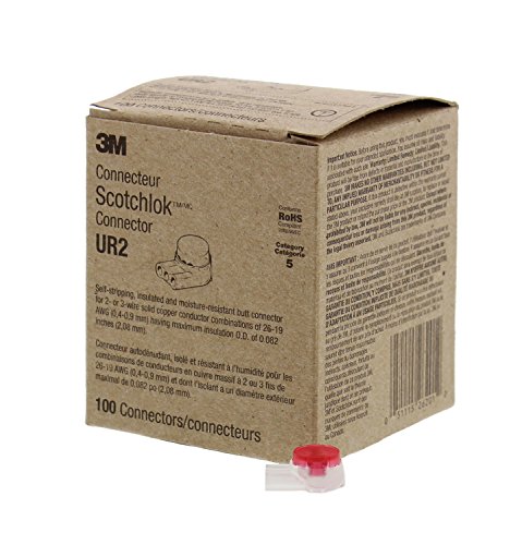
Looks like standard DSL, using a single pair phone line, with not termination block they used standard 3M Butt Connectors (http://amzn.to/2u7anpY). This wouldn't have been a real pro who did this though. Also your DSL speed has more to do with how far you are from the central equipment if they have upgraded it to higher speeds.
I did some contract DSL installation and ran into this type of stuff all the time, called out on a fixit call and some contractor before did something like this but more jank. Of they would call me out because there was someone who already tried but didn't know anything only to fix it with minimal effort on my part like, they would plug the DSL modem into the wrong phone drop (phone connection).
These work well, use them all the time, if you see an att technician out there you can ask him/her for a handful
http://www.amazon.com/gp/aw/d/B0076AY1PC/ref=mp_s_a_1_1?qid=1464033608&sr=8-1&pi=SY200_QL40&keywords=scotch+locks+3m&dpPl=1&dpID=615-Bg-jvAL&ref=plSrch
You, Sir... need to be turned on to these:
http://www.homedepot.com/p/Tyco-Electronics-DuraSeal-Butt-Splices-22-18-10-Clam-Heat-Shrink-CPGI-D-406-0001-10/202204344
They've got these, too... which are pretty awesome(Heatshrink with solder!):
https://www.amazon.com/Shrink-Solder-Sleeve-Crimpless-Connectors/dp/B01M1032A7
They are pc fans. I guess I am trying to find out if it is possible to use 2 of the 12v 1Amp drivers to run 3 fans at 12v and 666mA, instead of 1 driver that is currently running them at 12v 333mA to each fan. -- and keep from hitting them with 24v.
I am using wago connectors for my wiring. So if I just plugged in an additional driver, would this double the overall output to 24v 2Amps, or does it stay at 12v and just double the Amperage since each driver is only putting out 12v. ??
Also for splicing into wires, [Posi-taps] (http://www.amazon.com/gp/aw/d/B00389UT3I) work awesome
I'll have to go check, but they're standard 12v automotive relays. They look similar to these, which are actually cheaper. So, never mind, get them from Amazon.
It's not good for weak signals or high current connections. If you don't want to use proper crimp joints, solder the wires inline, either by twisting the bare strands around each other or by straightening the strands and pushing them together so they interleave. With the latter, it may help to spiral wind a single fine strand of wire around the joint. Applying rosin flux to the joint before soldering can help a lot. Cover the joint with a piece of heatshrink tubing that's at least 1.5" longer than the bare area, both for insulation and mechanical support (soldered stranded wire is prone to cracking).
Another possibility is SoldaSplice. It's heatshrink tubing with a ring of solder in the middle. You insert the wires and use a heat gun to both melt the solder and shrink the tubing.
So like a “vampire tooth”-connector?
Ginsco 120 Pcs/60 Pairs Quick Splice Wire Terminals T-Tap Self-stripping with Nylon Fully Insulated Male Quick Disconnects Kit https://www.amazon.com/dp/B01CDWC60Y/ref=cm_sw_r_cp_api_i_XIlTCbG08V4HF
Next time, order some butt connectors and a stripper/crimper. You need these tools anyway.
This https://smile.amazon.com/Shrink-Solder-Sleeve-Crimpless-Connectors/dp/B00IEFOCXO/ref=smi_www_rco2_go_smi_g3905707922?_encoding=UTF8&*Version*=1&*entries*=0&ie=UTF8&th=1
Sadly I don't know the type of connector this is, but would be interested to for other projects I have. I'm in need of some small in-line connectors like this.
[edit1] If I'm not mistaken though, it look like some kind of MOLEX brand connector.
[edit2] You could also just splice the wire and add an in-line extension with something like this. You can get them at any hardware store. These are the cripless kind and are a bit more expensive. The others you can get for a few $ if you've got a crimper.
I used a dual usb with a magnetic/water resistant closure and really like it. I’ll link it later when I get home if you want. I also tied into wires instead of direct to battery they make wire tie ins that just clamp on like this:
Ginsco 120 Pcs/60 Pairs Quick Splice Wire Terminals T-Tap Self-stripping with Nylon Fully Insulated Male Quick Disconnects Kit https://www.amazon.com/dp/B01CDWC60Y/ref=cm_sw_r_cp_api_i_n4bdBbTK9RZRB
You can pretty much do as you wish. You can normally put 2 or more wires in those clamp down terminals.
In my day, we'd use something like this to connect up our circuit.
Buy a couple of Wago connectors instead of wire nuts. They are much easier to work with and they don’t mess up the tip of your wires in case you have to modify anything inside there in the future.
https://www.amazon.com/Wago-221-415-LEVER-NUTS-Conductor-Connectors/dp/B06XH47DC2/ref=pd_aw_sbs_328_3/134-9665181-4117155?_encoding=UTF8&pd_rd_i=B06XH47DC2&pd_rd_r=8b3b9b4d-824e-11e9-b4c5-ef907af3647f&pd_rd_w=jREPn&pd_rd_wg=tI4UX&pf_rd_p=aae79475-6dc9-4a12-80e8-27b63108fa72&pf_rd_r=ZE23ZBS22K5W4JR9HFWN&psc=1&refRID=ZE23ZBS22K5W4JR9HFWN
Or
https://www.amazon.com/Wago-221-413-LEVER-NUTS-Conductor-Connectors/dp/B06XGYXVXR/ref=mp_s_a_1_fkmr2_1?keywords=wago+413+10+pk&qid=1559161061&s=gateway&sr=8-1-fkmr2
I prefer the 414 ones but couldn’t find them right now. They’re optimal in my view.
spade connectors and a crimper!
https://www.amazon.com/Yueton-100pcs-Insulated-Terminal-Connectors/dp/B010GWZOUW/ref=sr_1_23?keywords=spade+connectors+crimper&qid=1567634312&s=hi&sr=1-23
​
https://www.amazon.com/WGGE-Professional-crimping-Multi-Tool-Multi-Function/dp/B073YG65N2/ref=sr_1_4?keywords=wire+stripper+crimper&qid=1567634471&s=hi&sr=1-4
The connectors he used are 3M Scotchlok IDC connectors. They make wiring stupid easy, and I actually used them on my printer's replacement fan because I was lazy. You just slide red in, and red out into one, and crimp with pliers. Same for the ground wires. No wire stripping needed.
Info | Details
----|-------
Amazon Product | 3M Scotchlok IDC Butt Connector, 100 Pack Yellow
>Amazon donates 0.5% of the price of your eligible AmazonSmile purchases to the charitable organization of your choice. By using the link above you get to support a chairty and help keep this bot running through affiliate programs all at zero cost to you.
If you're going to do splicing around water I'd get some heat shrink tubing, it'll help at least. You could also get wire crimp connectors like these at most hardware stores: https://www.amazon.com/Wire-Crimp-Connectors-Blue-Yellow/dp/B002T1FLPM
You can buy the pi zero w with headers attached, just search on it. More expensive of course.
1.
Which wires specifically? In general, I was planning on going for heat-shrink solder terminal connectors and crimp connectors.
One of the reasons I posted this is because there are quite a few connectors and I am still not entirely 100% sure what I need. Obviously when screwing something in to a screw terminal block, the ring crimp connectors. But when joining wires, I would prefer to use the heat-shrink-solder type, but there are also butts and blades (heh).
I bought this set of terminals, figured I'd need them anyways: Assorted crimp terminals
I am probably going to buy this set of solder terminals: Fancy solder terminals
I am pretty good at soldering (though usually circuit boards, not automotive wires, hence not entirely knowing what to do.) I have easy access to a heat gun as well.
2.
Well, both - the breaker goes on the battery, and it sets the maximum amperage for the entire new fuse block and everything attached to it. The fuses go for each individual circuit. I want to use just one fuse for each circuit, instead of having several different circuits sitting on the same fuse, largely for my own desire for neatness and debug-ability. I could have one main fuse instead of the main breaker, but I figure that they will serve the same function and I may as well go for the re-usable option.
I was going to go for this breaker: Fat breaker
That said, I bought this fuse kit, which includes up to a 35A fuse, which will be more than enough. I also bought this fuse holder, in case I decide to use one main fuse instead of one main breaker. (I figured I'd need both of these anyways for some project, may as well get them even if I don't use them right now.)
Fuse Kit
In-line Fuse Holder
---
In general, I think my system will basically look like this:
Battery 12V + Breaker = safe 12V
Save 12V + ignition 12V (do I need a fuse here?) + Relay = ignition-switched 12V
Ignition-hot 12V + Fuse Block + ATC/ATO Fuses = eight fused circuits
Fused circuits, obviously, feeding from above. I will probably add a 20A switch in line with high-power circuits, just in case, as an emergency switch.
Fused circuits will terminate at something like this Ground Bar.
 
What do you think of this proposed setup?
I do realize that it's kind of overkill for what I want.
But you can probably agree that overkill is better than your car burning down!
If it doesn't have to be something that can be disconnected easily, then this might work: https://www.amazon.com/dp/B01M0EZBYQ
Practice on some spare wires first. Takes a bit of trial and error, but then works great.
Not being able to disconnect might be against code. But then, it's only low voltage. So, probably not a big deal
Ah makes sense, thanks for all the info!
So from a full day of research here's what I'm thinking:
2M of RBGW SK6812
Splitting them into 12 - 6 inch long strips. (Probably only use 6-8 but figured better to have more than not enough)
Battery power through 7.5A fuse (the strip is rated at 43W/m at 5V the next fuse is 10A so figured go lower to be safer?) and relay/switch tapped to ACC line run through 12v step down to 5v through ALITOVE bluetooth controller into wago connectors with diodes going to each strip
https://www.amazon.com/BTF-LIGHTING-Individually-Addressable-Flexible-Non-waterproof/dp/B079ZX7LY3/ref=sr_1_2?ie=UTF8&qid=1539729680&sr=8-2&keywords=rgbw%2Bsk6812&th=1
https://www.amazon.com/ALITOVE-Female-Connector-WS2812B-SK6812-RGBW/dp/B071H5XCN5/ref=sr_1_3?ie=UTF8&qid=1539737420&sr=8-3&keywords=LED+connector+3+pin
https://www.amazon.com/SMAKN-Converter-Power-Supply-Module/dp/B00CXKBJI2/ref=sr_1_3?ie=UTF8&qid=1539736197&sr=8-3&keywords=12v+step+down+to+5v
https://www.amazon.com/ALITOVE-Addressable-Controller-SK6812-RGBW-Programmable/dp/B07G77YD9L/ref=sr_1_1?ie=UTF8&qid=1539734109&sr=8-1&keywords=12v++SK6812
https://www.amazon.com/gp/product/B0107SYYGU/ref=oh_aui_detailpage_o01_s00?ie=UTF8&psc=1
Grab some quick connect clips
https://www.amazon.com/dp/B01L74LNCG/ref=cm_sw_r_cp_apa_i-k8BbBM5JN9F
They aren't permanent when you undo them it leaves a tiny splice in the wiring ... won't interfere with the function. Even after its removed.
I grabbed the hot and ground from the 12v round socket. Right in the center console. Next to the shifter. (Accessory hot only... only works when the key is on)
If you use a cheap 12v indicator it makes it easy to find a hot.
https://shop.advanceautoparts.com/p/project-pro-automotive-circuit-tester-tw1486-1486/25989105-p?c3ch=PLA&c3nid=25989105-P&adtype=pla&gclsrc=aw.ds&&gclid=CjwKCAiAlb_fBRBHEiwAzMeEdhcZcEoliWNoycOy6evFUQY5FACscUi3Myyt4Q3TqBG8oiMF-iTovBoCFQUQAvD_BwE
If you want a constant hot... grab the top left lead on your OBD2 port (even with your keys off you should have 12v power) I did it on my wife's prius so you can leave your device charging while the car is off.
Any ground will do.
If you need more help with the specifics just ask.
Note I am assuming that you have a general understanding of 12v DC (car electronics)
3M Scotchlok IDC Butt Connector, 100 Pack Yellow https://www.amazon.com/dp/B0076AY6J8/ref=cm_sw_r_cp_taa_nUp4BbHPMPP0X
Wago lever nuts are the way to go.
I'll even give you a link to the 5 port ones:
20 Amp 5 port.
30 Amp 5 port.
Just find some splice terminals like these: https://www.amazon.com/Ginsco-Terminals-Self-stripping-Insulated-Disconnects/dp/B01CDWC60Y/ref=sr_1_8?crid=2L6Z6JKOO7AAV&keywords=wire+tap+connectors&qid=1558381066&s=gateway&sprefix=wire+tap%2Caps%2C173&sr=8-8
Use them to connect a Power Magic Pro onto battery/switched/ground wires.
The 7-pin connector is specifically for trailers with brakes or other power requirements. The 4-pin connectors control lights only, the extra pins on the 7-pin actuate the breaks and provide extra power for things like charging breakaway boxes or running RV refrigerators.
Being a 40-foot trailer, I don't see how there is any way that it would not weigh enough to require brakes, no matter the state. There would be no way to rewire the trailer to use a 4-pin connector and actuate the brakes. Even having a 7-pin connector on the truck would be no guarantee that the brakes are being actuated - most require an aftermarket brake controller be wired in.
If you are comfortable with the lack of braking and just need to do short pulls, it would be a relatively simple process to parallel a 4-pin connector onto the 7-pin trailer wiring so that you could at least have lights. Something like this:
https://www.etrailer.com/Wiring/Wesbar/W787268.html?feed=npn&gclid=EAIaIQobChMIiPG_r8G_4AIVQ1YNCh3MwwHPEAQYASABEgKr5_D_BwE
with these
https://www.amazon.com/Ginsco-Terminals-Self-stripping-Insulated-Disconnects/dp/B01CDWC60Y
​
Your lights would work and you'd avoid the attention of the fuzz, but I'd be careful about running around without brakes on a 40-foot trailer very often.
Good luck!
​
EDIT: I ran across this that would solve your problem too, I think. A little clunkier, but plug and play. Same issue with not actually having brakes, though.
https://www.etrailer.com/Wiring/Mighty-Cord/A10-7084VP.html
I have that exact head unit. I hope you did not order it yet cause it sucks.
I would go with something from JVC or Clarion. Sony's also has some issues but it's not as slow as this Pioneer.
For connecting wires, I highly recommend the 3M scotchloks. https://www.amazon.com/3M-Scotchlok-Butt-Connector-Pack/dp/B0076AY1PC/ref=pd_sim_60_3?_encoding=UTF8&psc=1&refRID=GRPGJWV0YNVV628S0S1H
You should or will want to, use an amp for those speakers. This one from JL is affordable, good quality build, tiny and 4 channels,nice sound quality while being really small to fit anywhere: https://www.amazon.com/JL-Audio-MHX280-Compact-Amplifier/dp/B012ZNKQHQ
I think it sounds just as good as my pricier JL XD450/3 amp
Any wire you have will work. You can even use some spare CAT5 or cut up one of those telephone cords you seem to get with everything. Then just get a momentary switch. If you can solder, the rest is stupid easy.
To avoid trying to find connectors and crimp them, I would just extend the wires. If you don't want to mess with them, buy some scotchlok splices: http://smile.amazon.com/UY2-3M-Scotchlok-Butt-Connector-Pack/dp/B0076AY6J8 Just shove the 2 wires in and pinch with pliers. Takes longer to cut the wires than it does to splice them. If you talk nice to the installer for your internet/phone, he may have some that will fall off the truck.
I don't have any experience with any other crimpers than the ones I mentioned above but these are pretty highly rated. You might also consider using heat shrink/solder butt connectors. I've got the kit I linked to here and have been impressed with it. You will need a heat gun though but no crimping involved. Just use enough heat to melt the solder and shrink the heat shrink .
I can run with that I think. By using a relay like this (https://www.amazon.com/Auto-Truck-Relay-Socket-SPDT/dp/B007JPPQH6) I should be able to tie the 12v that starts the pump to the contacts 30(+) and 85(-), wires to the sensor to 85(-) and 87(+), and connect the 30(+) to 86(+) to trigger.
Forgive me if it sounds ignorant: is junction recommended for safety/neatness or is it a technical must, as opposed to twist-on wire nuts I thought of using? If it's a must, would it be something like these (terminal blocks):
https://www.amazon.com/Wago-221-415-LEVER-NUTS-Conductor-Connectors/dp/B06XH47DC2
https://www.galco.com/buy/Bussmann/TB100-04
I'll mount the sticks on the outside of the rim, bringing the wires along the spokes to the center of the wheel.
Oh those wire into the daytime running lights and the turn signal. I used these to make splicing easy. On mine the green wire is the turn signal and the red wire is the DRL, black is ground.
Look for 3M Scotchlok connectors, I bought these about a year ago and they're soooo useful